ESP32-Based Security System with Fingerprint Authentication and Environmental Monitoring
Circuit Documentation
Summary
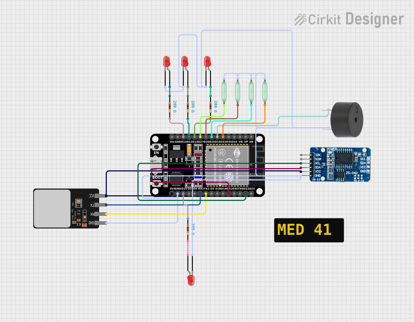
The circuit in question appears to be a security or monitoring system featuring a microcontroller (ESP32), a fingerprint scanner for authentication, a real-time clock (RTC DS3231) for timekeeping, multiple reed switches likely used for sensing door/window status, a buzzer for audible alerts, and several LEDs for visual indicators. The circuit uses resistors to limit current to the LEDs and possibly to pull-up/down other components. The ESP32 serves as the central processing unit, interfacing with the various sensors and output devices.
Component List
Microcontroller
- ESP32 (30 pin): A powerful microcontroller with Wi-Fi and Bluetooth capabilities, used as the central processing unit of the circuit.
Sensors
- Fingerprint Scanner: Used for biometric authentication.
- RTC DS3231: A real-time clock module for timekeeping.
- Reed Switches: Magnetic switches used to detect the opening and closing of doors or windows.
Output Devices
- Buzzer: An audible alert device.
- LEDs (Red): Visual indicators, likely used to show system status or alerts.
Passive Components
- Resistors (200 Ohms): Current-limiting resistors for the LEDs and possibly for pull-up/down configurations.
Wiring Details
ESP32 (30 pin)
- D32, D33, D25, D26, D27: Connected to reed switches for sensing door/window status.
- D14, D12, D13: Connected to resistors, which are then connected to LEDs.
- D22, D21: I2C communication pins connected to the RTC DS3231 (SCL and SDA).
- TX2, RX2: UART communication pins connected to the Fingerprint Scanner.
- GND: Common ground for the circuit.
- 3V3: Power supply for the Fingerprint Scanner and RTC DS3231.
Fingerprint Scanner
- VCC: Powered by the ESP32's 3V3 pin.
- TX, RX: UART communication with the ESP32.
- GND: Connected to the common ground.
RTC DS3231
- SCL, SDA: I2C communication with the ESP32.
- VCC: Powered by the ESP32's 3V3 pin.
- GND: Connected to the common ground.
LEDs (Red)
- Anode: Connected to the ESP32 through a 200 Ohm resistor.
- Cathode: Connected to the common ground.
Reed Switches
- Pin 1: Connected to various GPIO pins on the ESP32 for sensing.
- Pin 2: Connected to the common ground.
Buzzer
- PIN: Connected to a GPIO pin on the ESP32 for control.
- GND: Connected to the common ground.
Resistors (200 Ohms)
- Pin 1: Connected to the anode of LEDs.
- Pin 2: Connected to GPIO pins on the ESP32.
Documented Code
No code was provided for the microcontroller. The expected code would handle the initialization of the GPIO pins, setup of the I2C communication for the RTC, UART communication for the fingerprint scanner, and logic for reading the reed switches and controlling the buzzer and LEDs based on the system status.
Please note that without the actual code, the functionality described above is assumed based on the typical use of the components and the wiring details provided.