Cirkit Designer
Your all-in-one circuit design IDE
Home /
Project Documentation
Arduino-Controlled GSM and Relay Interaction System
Circuit Documentation
Summary
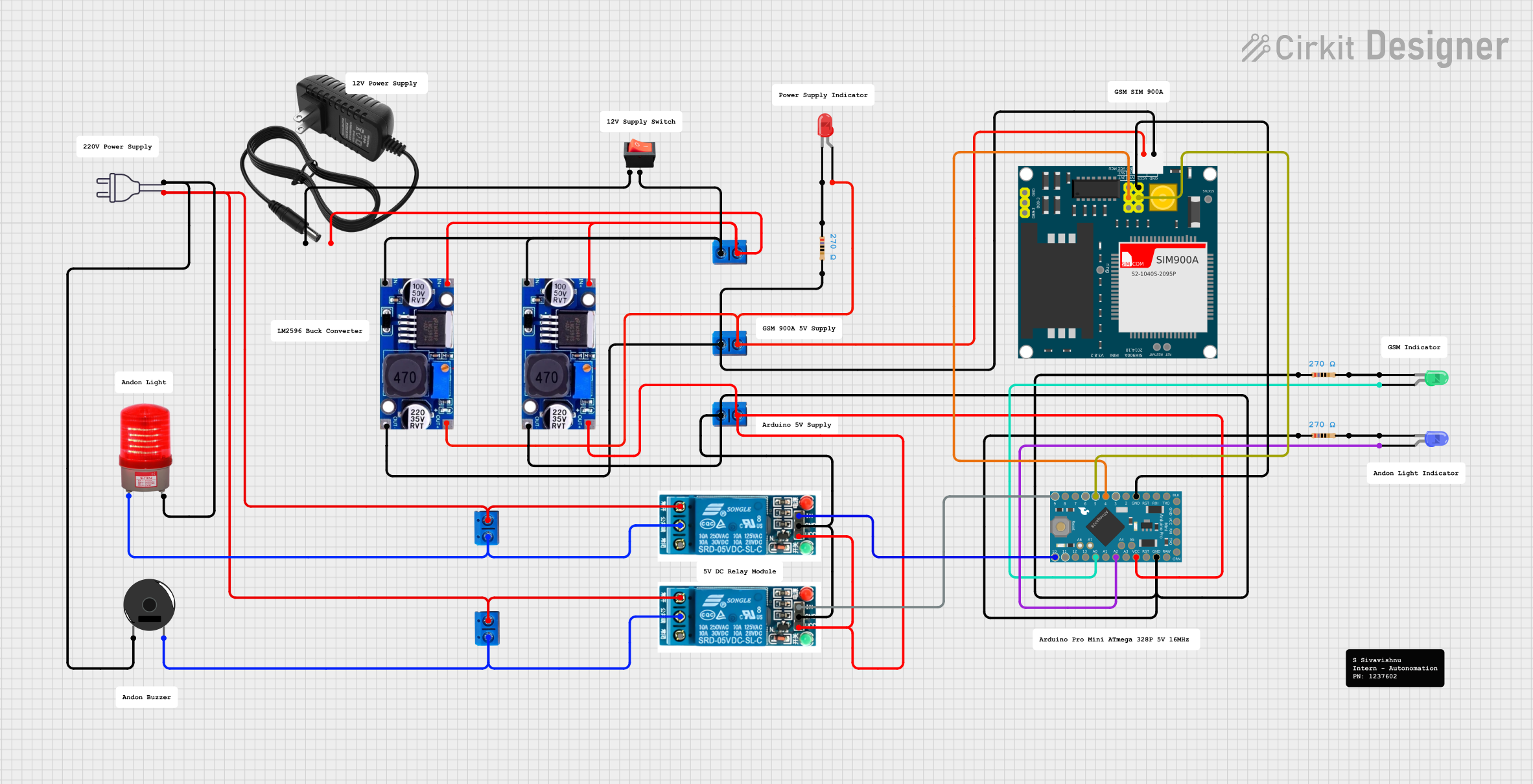
This document provides a detailed overview of a circuit designed to interface an Arduino Pro Mini with a SIM900A GSM module, various LEDs, relays, and other components. The circuit is powered by a 12V power supply, regulated down to 5V using LM2596 voltage regulators. It includes indicators (LEDs), a piezo buzzer, and a 220VAC red light for visual and audible feedback. The circuit can control AC loads via relays and has a rocker switch for power control.
Component List
Microcontroller
- Arduino Pro Mini: A compact microcontroller board based on the ATmega328, used for controlling the logic of the circuit.
Communication Module
- SIM900A: A GSM/GPRS module for cellular communication.
Indicators
- LED: Two Pin (red): A red LED used as an indicator.
- LED: Two Pin (blue): A blue LED used as an indicator.
- LED: Two Pin (green): A green LED used as an indicator.
- red light 220vac: A 220VAC red light indicator.
Power Supply Components
- 12v power supply: Provides the main power source for the circuit.
- LM2596: A voltage regulator module used to step down the voltage to 5V.
Switches and Relays
- 5v relay: Electromechanical switches used to control high power devices.
- rocker switch: A manual switch used to control the power supply to the circuit.
Sound Indicator
- Piezo Buzzer: An electronic device that emits a tone when powered.
Connectors
- Terminal PCB 2 Pin: Connectors used for making electrical connections to the board.
Resistors
- Resistor: Three resistors with a resistance of 270 Ohms, used for current limiting to the LEDs.
Miscellaneous
- Comment: Placeholder for additional notes or comments in the circuit.
Wiring Details
Arduino Pro Mini
- D5: Connected to SIM900A 5VR.
- GND: Common ground with SIM900A, 5V relays, and resistors.
- VCC: Connected to the output of LM2596 voltage regulator.
- A2: Connected to the anode of the blue LED.
- A0: Connected to the anode of the green LED.
- D10: Controls the "In" pin of one 5V relay.
- D9: Controls the "In" pin of another 5V relay.
SIM900A GSM Module
- GND: Common ground with Arduino Pro Mini, resistors, and 5V relays.
- 5V: Connected to the output of LM2596 voltage regulator.
- 5VR: Connected to Arduino Pro Mini D5.
- 5VT: Connected to Arduino Pro Mini D4.
LEDs
- Red LED: Anode connected to SIM900A 5V, cathode connected through a 270 Ohm resistor to ground.
- Blue LED: Anode connected to Arduino Pro Mini A2, cathode connected through a 270 Ohm resistor to ground.
- Green LED: Anode connected to Arduino Pro Mini A0, cathode connected through a 270 Ohm resistor to ground.
5V Relays
- GND: Common ground with Arduino Pro Mini and resistors.
- VCC: Connected to the output of LM2596 voltage regulator.
- In: Controlled by Arduino Pro Mini D10 and D9 for two separate relays.
- Common terminal: Connected to the neutral wire of the power 220V and to the Piezo Buzzer.
- Normally Open: Connected to the hot wire of the power 220V and to the red light 220VAC.
Power Supply Components
- 12V Power Supply: Provides power to the circuit, connected to the rocker switch and LM2596 voltage regulators.
- LM2596: Steps down the voltage from 12V to 5V, powering the Arduino Pro Mini, SIM900A, and 5V relays.
Rocker Switch
- Input: Connected to the positive terminal of the 12V power supply.
- Output: Connected to the input of LM2596 voltage regulators.
Piezo Buzzer
- Pin 1: Connected to the neutral wire of the power 220V.
- Pin 2: Connected to the common terminal of the 5V relay.
Red Light 220VAC
- +: Connected to the common terminal of the 5V relay.
- -: Connected to the neutral wire of the power 220V.
Documented Code
Arduino Pro Mini Code (sketch.ino)
void setup() {
  // put your setup code here, to run once:

}

void loop() {
  // put your main code here, to run repeatedly:

}
Note: The provided code is a template and does not contain any functional logic specific to the circuit. It needs to be populated with the appropriate setup and loop code to control the circuit components as intended.