
Arduino Mega 2560-Based Smart Irrigation System with Soil Moisture and Rain Sensors
View and Edit Project In Cirkit Designer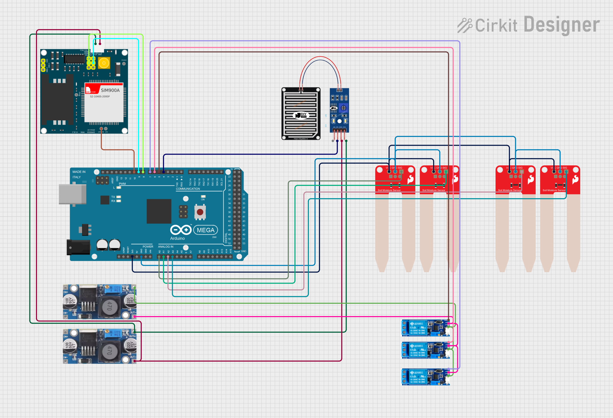
Circuit Documentation
Summary
This circuit is designed to interface an Arduino Mega 2560 with multiple sensors and modules, including soil moisture sensors, a rain sensor, relay modules, and a SIM900A module. The circuit is powered through step-down buck converters to ensure appropriate voltage levels for the components.
Component List
Arduino Mega 2560
- Description: A microcontroller board based on the ATmega2560.
- Pins: IOREF, RESET, 3V3, 5V, GND, VIN, A0-A15, D0-D53, PWM, AREF, SDA, SCL
SparkFun Soil Moisture Sensor
- Description: A sensor used to measure the moisture level in the soil.
- Pins: VCC, GND, SIG
RAIN SENSOR
- Description: A sensor used to detect the presence of rain.
- Pins: AO, DO, GRD, VCC
Step down Buck converter
- Description: A DC-DC converter used to step down voltage.
- Pins: IN +, IN - GND, OUT +, OUT - GND
Relay module 5v-30v
- Description: A relay module used to control high voltage devices.
- Pins: common contact, normally open, normally closed, trigger, V-, V+
SIM900A
- Description: A GSM/GPRS module used for communication.
- Pins: GND, DB9-3 (RXD), DB9-2 (TXD), 5V, 3VR, 5VR, 3VT, 5VT, VCC, Ring, RESTART, RESET, STATUS
Wiring Details
Arduino Mega 2560
3V3
- Connected to VCC of all SparkFun Soil Moisture Sensors
GND
- Connected to GND of all SparkFun Soil Moisture Sensors
A0
- Connected to SIG of one SparkFun Soil Moisture Sensor
A1
- Connected to SIG of another SparkFun Soil Moisture Sensor
A2
- Connected to SIG of another SparkFun Soil Moisture Sensor
A3
- Connected to SIG of another SparkFun Soil Moisture Sensor
D4 PWM
- Connected to DO of the RAIN SENSOR
D5 PWM
- Connected to trigger of one Relay module
D6 PWM
- Connected to trigger of another Relay module
D7 PWM
- Connected to trigger of another Relay module
D8 PWM
- Connected to 5VT of the SIM900A
D9 PWM
- Connected to 5VR of the SIM900A
D10 PWM
- Connected to RESTART of the SIM900A
SparkFun Soil Moisture Sensor
VCC
- Connected to 3V3 of the Arduino Mega 2560
GND
- Connected to GND of the Arduino Mega 2560
SIG
- Connected to A0, A1, A2, or A3 of the Arduino Mega 2560 (one sensor per pin)
RAIN SENSOR
DO
- Connected to D4 PWM of the Arduino Mega 2560
GRD
- Connected to GND of the Step down Buck converter
VCC
- Connected to OUT + of the Step down Buck converter
Step down Buck converter
OUT +
- Connected to V+ of all Relay modules
- Connected to VCC of the RAIN SENSOR
- Connected to 5V of the SIM900A
OUT - GND
- Connected to V- of all Relay modules
- Connected to GND of the SIM900A
- Connected to GRD of the RAIN SENSOR
Relay module 5v-30v
trigger
- Connected to D5 PWM, D6 PWM, or D7 PWM of the Arduino Mega 2560 (one relay per pin)
V+
- Connected to OUT + of the Step down Buck converter
V-
- Connected to OUT - GND of the Step down Buck converter
SIM900A
5VT
- Connected to D8 PWM of the Arduino Mega 2560
5VR
- Connected to D9 PWM of the Arduino Mega 2560
RESTART
- Connected to D10 PWM of the Arduino Mega 2560
GND
- Connected to OUT - GND of the Step down Buck converter
5V
- Connected to OUT + of the Step down Buck converter
Documented Code
Arduino Mega 2560 Code (sketch.ino)
void setup() {
  // put your setup code here, to run once:

}

void loop() {
  // put your main code here, to run repeatedly:

}
Additional Documentation (documentation.txt)