Arduino UNO-Based Proximity Alert System with Ultrasonic Sensor, Servo, LED, and Buzzer
Circuit Documentation
Summary
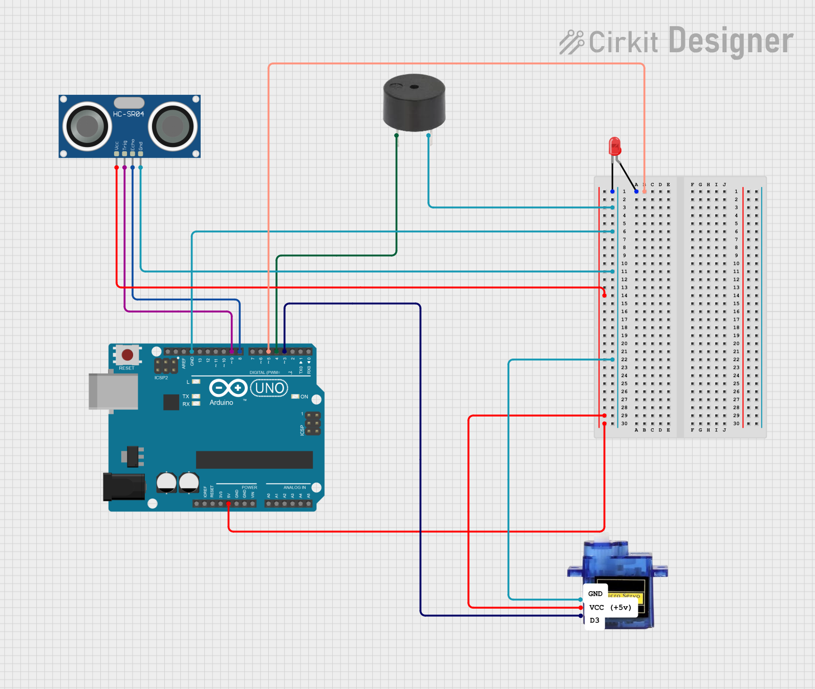
This circuit utilizes an Arduino UNO microcontroller to control an HC-SR04 Ultrasonic Sensor, a red LED, a micro servo motor, and a buzzer. The ultrasonic sensor measures distance, and based on the distance, the microcontroller controls the servo motor, LED, and buzzer. If an object is detected within 10 cm, the servo rotates to 90 degrees, the LED lights up, and the buzzer sounds. Otherwise, the servo resets to 0 degrees, the LED turns off, and the buzzer is silent.
Component List
Arduino UNO
- Description: A microcontroller board based on the ATmega328P.
- Pins: UNUSED, IOREF, Reset, 3.3V, 5V, GND, Vin, A0, A1, A2, A3, A4, A5, SCL, SDA, AREF, D13, D12, D11, D10, D9, D8, D7, D6, D5, D4, D3, D2, D1, D0
LED: Two Pin (red)
- Description: A red LED with two pins: anode and cathode.
- Pins: cathode, anode
HC-SR04 Ultrasonic Sensor
- Description: An ultrasonic sensor used for distance measurement.
- Pins: VCC, TRIG, ECHO, GND
Micro servo 9G
- Description: A small servo motor used for precise control of angular position.
- Pins: GND, +5V, PWM
Buzzer
- Description: A simple buzzer used for sound output.
- Pins: PIN, GND
Wiring Details
Arduino UNO
5V connected to:
- HC-SR04 Ultrasonic Sensor (VCC)
- Micro servo 9G (+5V)
GND connected to:
- LED: Two Pin (red) (cathode)
- HC-SR04 Ultrasonic Sensor (GND)
- Micro servo 9G (GND)
- Buzzer (GND)
D9 connected to:
- HC-SR04 Ultrasonic Sensor (TRIG)
D8 connected to:
- HC-SR04 Ultrasonic Sensor (ECHO)
D5 connected to:
- LED: Two Pin (red) (anode)
D4 connected to:
- Buzzer (PIN)
D3 connected to:
- Micro servo 9G (PWM)
LED: Two Pin (red)
cathode connected to:
- Arduino UNO (GND)
anode connected to:
- Arduino UNO (D5)
HC-SR04 Ultrasonic Sensor
VCC connected to:
- Arduino UNO (5V)
TRIG connected to:
- Arduino UNO (D9)
ECHO connected to:
- Arduino UNO (D8)
GND connected to:
- Arduino UNO (GND)
Micro servo 9G
GND connected to:
- Arduino UNO (GND)
+5V connected to:
- Arduino UNO (5V)
PWM connected to:
- Arduino UNO (D3)
Buzzer
PIN connected to:
- Arduino UNO (D4)
GND connected to:
- Arduino UNO (GND)
Code Documentation
#include <Servo.h>

// Define pins for HC-SR04
const int trigPin = 9;
const int echoPin = 8;

// Define pins for buzzer and LED
const int buzzerPin = 4;
const int ledPin = 5;

// Define variables for duration and distance
long duration;
int distance;

// Create servo object
Servo myServo;

void setup() {
  // Initialize serial communication
  Serial.begin(9600);

  // Set pin modes
  pinMode(trigPin, OUTPUT);
  pinMode(echoPin, INPUT);
  pinMode(buzzerPin, OUTPUT);
  pinMode(ledPin, OUTPUT);

  // Attach servo to pin 3
  myServo.attach(3);

  // Initialize servo position and outputs
  myServo.write(0);
  digitalWrite(buzzerPin, LOW);
  digitalWrite(ledPin, LOW);
}

void loop() {
  // Send a 10-microsecond pulse to the trigPin
  digitalWrite(trigPin, LOW);
  delayMicroseconds(2);
  digitalWrite(trigPin, HIGH);
  delayMicroseconds(10);
  digitalWrite(trigPin, LOW);

  // Read the echoPin and calculate the distance
  duration = pulseIn(echoPin, HIGH);
  distance = duration * 0.034 / 2; // Convert to cm

  // Print the distance to the Serial Monitor
  Serial.print("Distance: ");
  Serial.print(distance);
  Serial.println(" cm");

  // Control servo, buzzer, and LED based on distance
  if (distance < 10) {
    myServo.write(90); // Rotate servo to 90 degrees
    digitalWrite(buzzerPin, HIGH); // Activate buzzer
    digitalWrite(ledPin, HIGH);    // Turn on LED
    Serial.println("Object detected: Servo at 90 degrees, Buzzer ON, LED ON");
  } else {
    myServo.write(0); // Reset servo to 0 degrees
    digitalWrite(buzzerPin, LOW); // Deactivate buzzer
    digitalWrite(ledPin, LOW);    // Turn off LED
    Serial.println("No object: Servo at 0 degrees, Buzzer OFF, LED OFF");
  }

  // Small delay for stability
  delay(200);
}
This code initializes the pins and components in the setup() function and continuously measures the distance using the HC-SR04 sensor in the loop() function. Based on the measured distance, it controls the servo motor, LED, and buzzer.