
Raspberry Pi Pico Controlled Robot with Ultrasonic Sensing and Light Detection
View and Edit Project In Cirkit Designer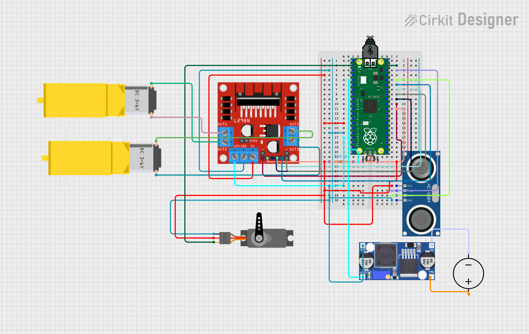
Circuit Documentation
Summary
This document provides a detailed overview of a circuit that includes a Raspberry Pi Pico microcontroller as the central processing unit. The circuit is designed to interface with various sensors and actuators, including a photocell (LDR), an HC-SR04 ultrasonic sensor, servo motors, gearmotors, and a motor driver (L298N). Power management is handled by a USB power source, a buck converter, and a DC power source. The Raspberry Pi Pico is programmed to control and interact with these components, as outlined in the embedded code section.
Component List
Raspberry Pi Pico
- Microcontroller board based on the RP2040 microcontroller chip.
- Features multiple GPIO pins for interfacing with various peripherals.
Photocell (LDR)
- A light-dependent resistor that changes resistance based on light intensity.
- Used for sensing light levels in the environment.
Resistor
- A 200 Ohm resistor used for current limiting or voltage division.
- Typically used in conjunction with sensors like the photocell.
HC-SR04 Ultrasonic Sensor
- An ultrasonic ranging module that provides 2cm to 400cm non-contact measurement functionality.
- Utilizes ultrasonic waves to measure distance to an object.
Gearmotor DC (Motorreductor)
- A DC motor with a gearbox for increased torque.
- Used for driving mechanical loads.
Servo
- A rotary actuator or linear actuator that allows for precise control of angular or linear position.
- Commonly used for steering mechanisms or small position control.
USB Power
- A power source that provides power through a USB interface.
- Used to power the Raspberry Pi Pico and other components.
L298N DC Motor Driver
- A motor driver module capable of driving two DC motors or one stepper motor.
- Provides the necessary current and voltage for motor operation.
Buck Converter
- A DC-DC converter that steps down voltage from a higher level to a lower level.
- Used to provide the appropriate voltage levels to different components.
DC Power Source
- A power supply that provides a DC voltage.
- Used as the main power source for the circuit.
Wiring Details
Raspberry Pi Pico
- Pin 39 connected to Servo (PWM signal)
- Pin 38 connected to HC-SR04 Ultrasonic Sensor (TRIG)
- Pin 17 connected to Photocell (LDR) and Resistor (forming a voltage divider)
- Pin 36 connected to HC-SR04 Ultrasonic Sensor (ECHO)
- Pins 35, 34, 33, 32, 31, 30 connected to L298N DC Motor Driver (control signals)
- Pin 14 connected to Photocell (LDR), HC-SR04 Ultrasonic Sensor, L298N DC Motor Driver, and Servo (VCC)
- Pin 16 connected to Resistor, HC-SR04 Ultrasonic Sensor, L298N DC Motor Driver, and Servo (GND)
Photocell (LDR)
- One pin connected to Raspberry Pi Pico (pin 17) and Resistor
- Other pin connected to Raspberry Pi Pico (pin 14) for power
Resistor
- One pin connected to Photocell (LDR)
- Other pin connected to Raspberry Pi Pico (pin 16) for ground
HC-SR04 Ultrasonic Sensor
- TRIG connected to Raspberry Pi Pico (pin 38)
- ECHO connected to Raspberry Pi Pico (pin 36)
- VCC connected to Raspberry Pi Pico (pin 14) for power
- GND connected to Raspberry Pi Pico (pin 16) for ground
Gearmotor DC (Motorreductor)
- Two instances of Gearmotor DC, each connected to two output pins of the L298N DC Motor Driver
Servo
- PWM connected to Raspberry Pi Pico (pin 39)
- VCC connected to Raspberry Pi Pico (pin 14) for power
- GND connected to Raspberry Pi Pico (pin 16) for ground
L298N DC Motor Driver
- Control inputs (IN1, IN2, IN3, IN4, ENA, ENB) connected to Raspberry Pi Pico
- Motor outputs (OUT1, OUT2, OUT3, OUT4) connected to Gearmotor DC
- Power inputs (12V, 5V) connected to Buck Converter and Raspberry Pi Pico
- Ground (GND) connected to Raspberry Pi Pico (pin 16)
Buck Converter
- IN+ and IN- connected to DC Power Source
- OUT+ connected to Raspberry Pi Pico (pin 17) and L298N DC Motor Driver
- OUT- connected to Raspberry Pi Pico (pin 16)
DC Power Source
- Positive connected to Buck Converter (IN+)
- Ground connected to Buck Converter (IN-)
Documented Code
Raspberry Pi Pico (sketch.ino)
void setup() {
  // put your setup code here, to run once:

}

void loop() {
  // put your main code here, to run repeatedly:

}
Raspberry Pi Pico (documentation.txt)
No additional code documentation provided.