
Circuit Documentation
Summary of the Circuit
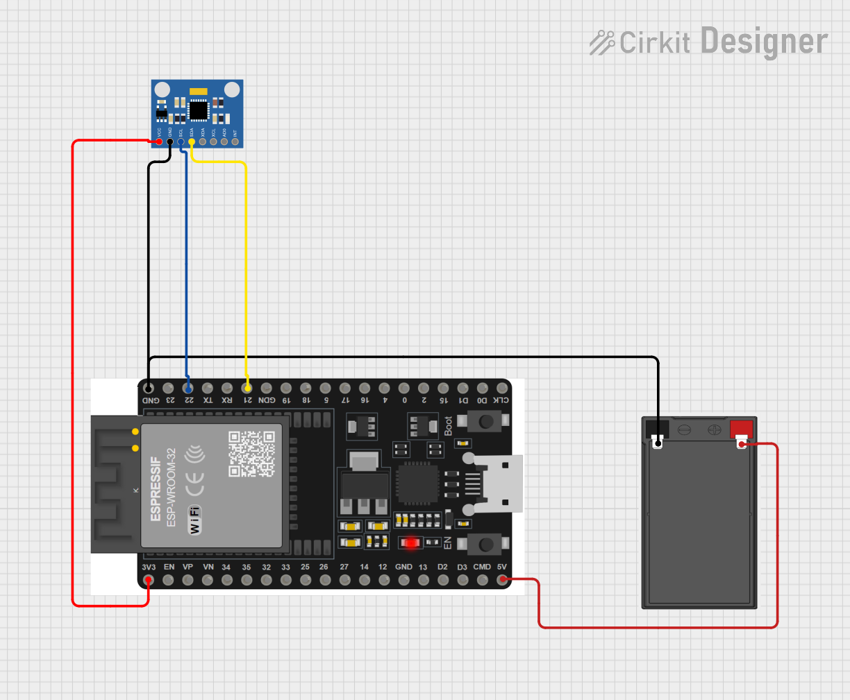
This circuit integrates an ESP32 microcontroller with an MPU6050 accelerometer and gyroscope sensor module, powered by a battery. The ESP32 serves as the central processing unit, capable of communicating with the MPU6050 via I2C protocol to read motion data. The battery provides the necessary power to the ESP32 and the MPU6050 sensor. The ESP32's 3.3V output is used to power the MPU6050, ensuring compatibility with the sensor's voltage requirements.
Component List
ESP32 38 PINS
- Description: A microcontroller with Wi-Fi and Bluetooth capabilities, featuring a wide range of GPIO pins.
- Pins: GND, 23, 22/SCL, 1, 2, 21/SDA, 19, 18, 5, 17/TX2, 16/RX2, 4, 0, 15, D1, D0, CLK, 3V3, EN, VP, VN, 34, 35, 32, 33, 25, 26, 27, 14, 12, 13, D2, D3, 11, 5V/VIN
MPU6050 Accelerometer + Gyroscope (Wokwi Compatible)
- Description: A sensor module that provides 3-axis gyroscope and 3-axis accelerometer readings.
- Pins: INT, AD0, XCL, XDA, SDA, SCL, GND, VCC
Battery
- Description: A power source for the circuit.
- Pins: -, +
Wiring Details
ESP32 38 PINS
- GND connected to Battery (-) and MPU6050 GND
- 22/SCL connected to MPU6050 SCL
- 21/SDA connected to MPU6050 SDA
- 3V3 connected to MPU6050 VCC
- 5V/VIN connected to Battery (+)
MPU6050 Accelerometer + Gyroscope (Wokwi Compatible)
- GND connected to ESP32 GND
- SCL connected to ESP32 22/SCL
- SDA connected to ESP32 21/SDA
- VCC connected to ESP32 3V3
Battery
- - connected to ESP32 GND
- + connected to ESP32 5V/VIN
Documented Code
sketch.ino
void setup() {
  // put your setup code here, to run once:

}

void loop() {
  // put your main code here, to run repeatedly:

}
documentation.txt
(No additional documentation provided)