
Arduino UNO-Based Smart Robotic System with IR Sensors and Motor Control
View and Edit Project In Cirkit Designer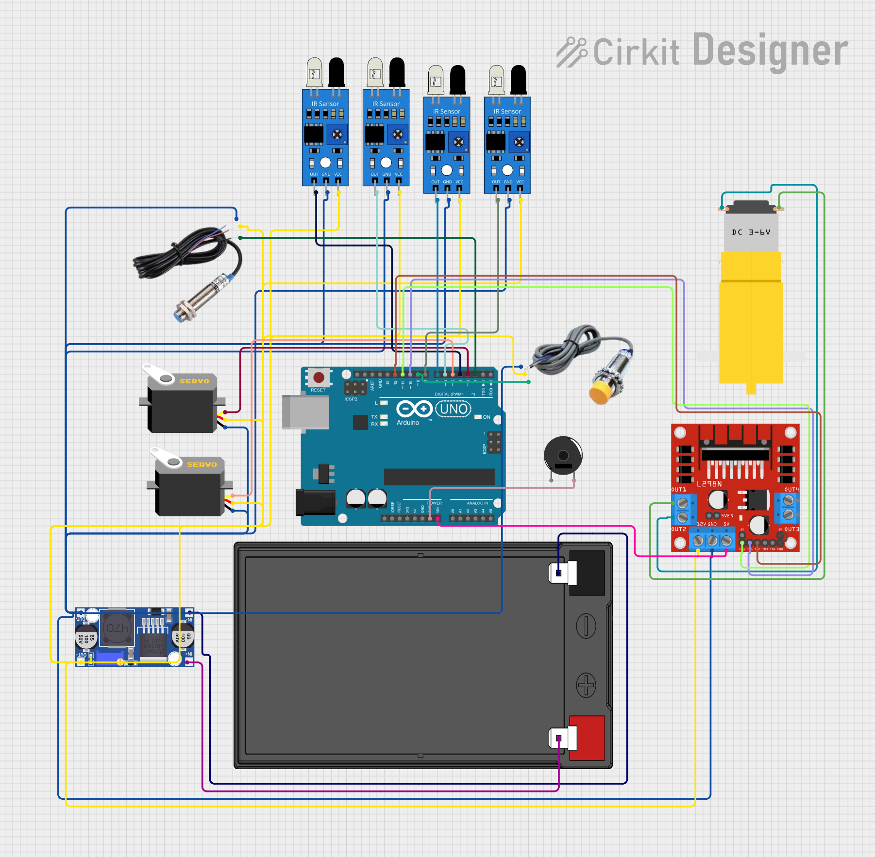
Circuit Documentation
Summary
This document provides a detailed overview of a circuit that includes an Arduino UNO microcontroller, multiple sensors (IR, capacitive, and inductive), a piezo buzzer, servos, a motor driver, a buck converter, and a 12V battery. The circuit is designed to interface various sensors and actuators with the Arduino UNO, which controls the components based on the input from the sensors.
Component List
Arduino UNO
- Description: A microcontroller board based on the ATmega328P.
- Pins: UNUSED, IOREF, Reset, 3.3V, 5V, GND, Vin, A0, A1, A2, A3, A4, A5, SCL, SDA, AREF, D13, D12, D11, D10, D9, D8, D7, D6, D5, D4, D3, D2, D1, D0
IR Sensor
- Description: Infrared sensor for object detection.
- Pins: out, gnd, vcc
Piezo Buzzer
- Description: A small audio signaling device.
- Pins: pin 1, pin 2
Servo
- Description: A small motor with a feedback mechanism for precise control.
- Pins: gnd, vcc, pulse
12V 7Ah Battery
- Description: A rechargeable battery providing 12V output.
- Pins: 12v +, 12v -
Motor amarillo motorreductor hobby
- Description: A small DC motor with a gearbox.
- Pins: vcc, GND
L298N DC Motor Driver
- Description: A dual H-Bridge motor driver.
- Pins: OUT1, OUT2, 12V, GND, 5V, OUT3, OUT4, 5V-ENA-JMP-I, 5V-ENA-JMP-O, +5V-J1, +5V-J2, ENA, IN1, IN2, IN3, IN4, ENB
Inductive Sensor
- Description: A sensor that detects metallic objects.
- Pins: Signal, VCC, GND
Capacitive Sensor
- Description: A sensor that detects non-metallic objects.
- Pins: GND, VCC, SIGNAL
Buck Converter
- Description: A DC-DC converter that steps down voltage.
- Pins: IN+, IN-, OUT+, OUT-
Wiring Details
Arduino UNO
- GND connected to Piezo Buzzer pin 2
- Vin connected to L298N DC Motor Driver 5V
- D12 connected to L298N DC Motor Driver IN2
- D11 connected to L298N DC Motor Driver ENA
- D10 connected to L298N DC Motor Driver IN1
- D9 connected to Capacitive Sensor SIGNAL
- D8 connected to IR Sensor out
- D7 connected to IR Sensor out
- D6 connected to IR Sensor out
- D5 connected to Servo pulse
- D4 connected to IR Sensor out
- D3 connected to Servo pulse
- D2 connected to Inductive Sensor Signal
IR Sensor
- out connected to Arduino UNO D8
- out connected to Arduino UNO D7
- out connected to Arduino UNO D6
- out connected to Arduino UNO D4
- gnd connected to Buck Converter OUT-
- vcc connected to Buck Converter OUT+
Piezo Buzzer
- pin 2 connected to Arduino UNO GND
Servo
- pulse connected to Arduino UNO D5
- pulse connected to Arduino UNO D3
- gnd connected to Buck Converter OUT-
- vcc connected to Buck Converter OUT+
12V 7Ah Battery
- 12v + connected to Buck Converter IN+
- 12v - connected to Buck Converter IN-
Motor amarillo motorreductor hobby
- vcc connected to L298N DC Motor Driver OUT1
- GND connected to L298N DC Motor Driver OUT2
L298N DC Motor Driver
- 5V connected to Arduino UNO Vin
- IN2 connected to Arduino UNO D12
- ENA connected to Arduino UNO D11
- IN1 connected to Arduino UNO D10
- 12V connected to Buck Converter OUT+
- GND connected to Buck Converter OUT-
- OUT1 connected to Motor amarillo motorreductor hobby vcc
- OUT2 connected to Motor amarillo motorreductor hobby GND
- +5V-J2 connected to ENB
Inductive Sensor
- Signal connected to Arduino UNO D2
- GND connected to Buck Converter OUT-
- VCC connected to Buck Converter OUT+
Capacitive Sensor
- SIGNAL connected to Arduino UNO D9
- GND connected to Buck Converter OUT-
- VCC connected to Buck Converter OUT+
Buck Converter
- OUT+ connected to Capacitive Sensor VCC, IR Sensor vcc, Servo vcc, Inductive Sensor VCC, L298N DC Motor Driver 12V
- OUT- connected to Capacitive Sensor GND, IR Sensor gnd, Servo gnd, Inductive Sensor GND, L298N DC Motor Driver GND
- IN+ connected to 12V 7Ah Battery 12v +
- IN- connected to 12V 7Ah Battery 12v -
Documented Code
Arduino UNO Code (sketch.ino)
void setup() {
  // put your setup code here, to run once:

}

void loop() {
  // put your main code here, to run repeatedly:

}
Additional Documentation (documentation.txt)