
Dual Motor Control Circuit with Directional Switching and Voltage Regulation
View and Edit Project In Cirkit Designer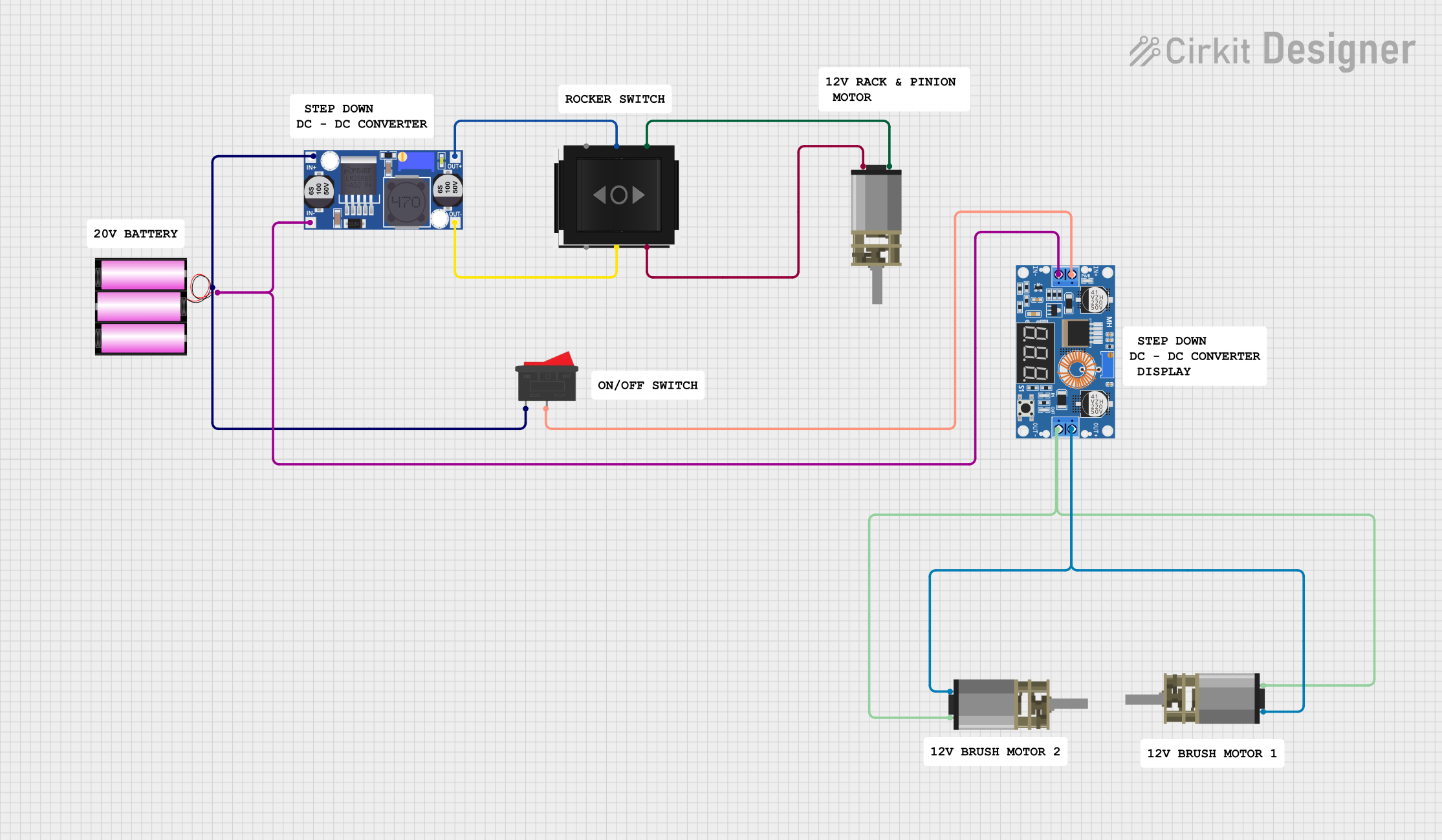
Circuit Documentation
Summary of the Circuit
This circuit is designed to control multiple DC Mini Metal Gear Motors using a step-down buck converter and directional switches. The buck converter steps down the voltage from a 12V battery to a lower voltage suitable for the motors. The rocker switch is used to turn the power supply on and off, while the directional switches control the direction of the motors by selectively providing power to either the IN1 or IN2 inputs of the motors.
Component List
XL4015 5A DC Buck Step-down
- Description: A DC-DC step-down (buck) converter module capable of driving a 5A load with high efficiency.
- Pins: Output +, Output -, Input +, Input -
Rocker Switch
- Description: A simple on-off switch to control the power flow in the circuit.
- Pins: 1, 2
DC Mini Metal Gear Motor
- Description: A compact and powerful DC motor with a metal gearbox for driving mechanical loads.
- Pins: IN1, IN2
Directional Switch
- Description: A switch that allows the direction of a motor to be controlled by selecting between two output lines.
- Pins: Out 2, IN, Out 1
Buck Converter
- Description: Another DC-DC step-down (buck) converter module.
- Pins: IN+, IN-, OUT+, OUT-
Battery 12V
- Description: A 12V battery providing the power source for the circuit.
- Pins: +, -
Wiring Details
XL4015 5A DC Buck Step-down
- Output +: Connected to IN1 of two DC Mini Metal Gear Motors.
- Output -: Connected to IN2 of two DC Mini Metal Gear Motors.
- Input +: Connected to Rocker Switch pin 2.
- Input -: Connected to the negative terminal of the 12V battery and IN- of the Buck Converter.
Rocker Switch
- Pin 1: Connected to the positive terminal of the 12V battery and IN+ of the Buck Converter.
- Pin 2: Connected to Input + of the XL4015 5A DC Buck Step-down.
DC Mini Metal Gear Motor
- IN1: One motor connected to Output + of the XL4015 5A DC Buck Step-down, another motor connected to Out 1 of a Directional Switch.
- IN2: One motor connected to Output - of the XL4015 5A DC Buck Step-down, another motor connected to Out 2 of a Directional Switch.
Directional Switch
- IN: Connected to OUT+ and OUT- of the Buck Converter.
- Out 1: Connected to IN1 of a DC Mini Metal Gear Motor.
- Out 2: Connected to IN2 of a DC Mini Metal Gear Motor.
Buck Converter
- IN+: Connected to the positive terminal of the 12V battery and Rocker Switch pin 1.
- IN-: Connected to the negative terminal of the 12V battery.
- OUT+: Connected to IN of a Directional Switch.
- OUT-: Connected to IN of another Directional Switch.
Battery 12V
- +: Connected to Rocker Switch pin 1 and IN+ of the Buck Converter.
- -: Connected to the negative terminal of the XL4015 5A DC Buck Step-down and IN- of the Buck Converter.
Documented Code
There is no embedded code provided for any microcontrollers in this circuit. If in the future, the circuit is updated to include a microcontroller, the code will be documented in this section.