
Circuit Documentation
Summary
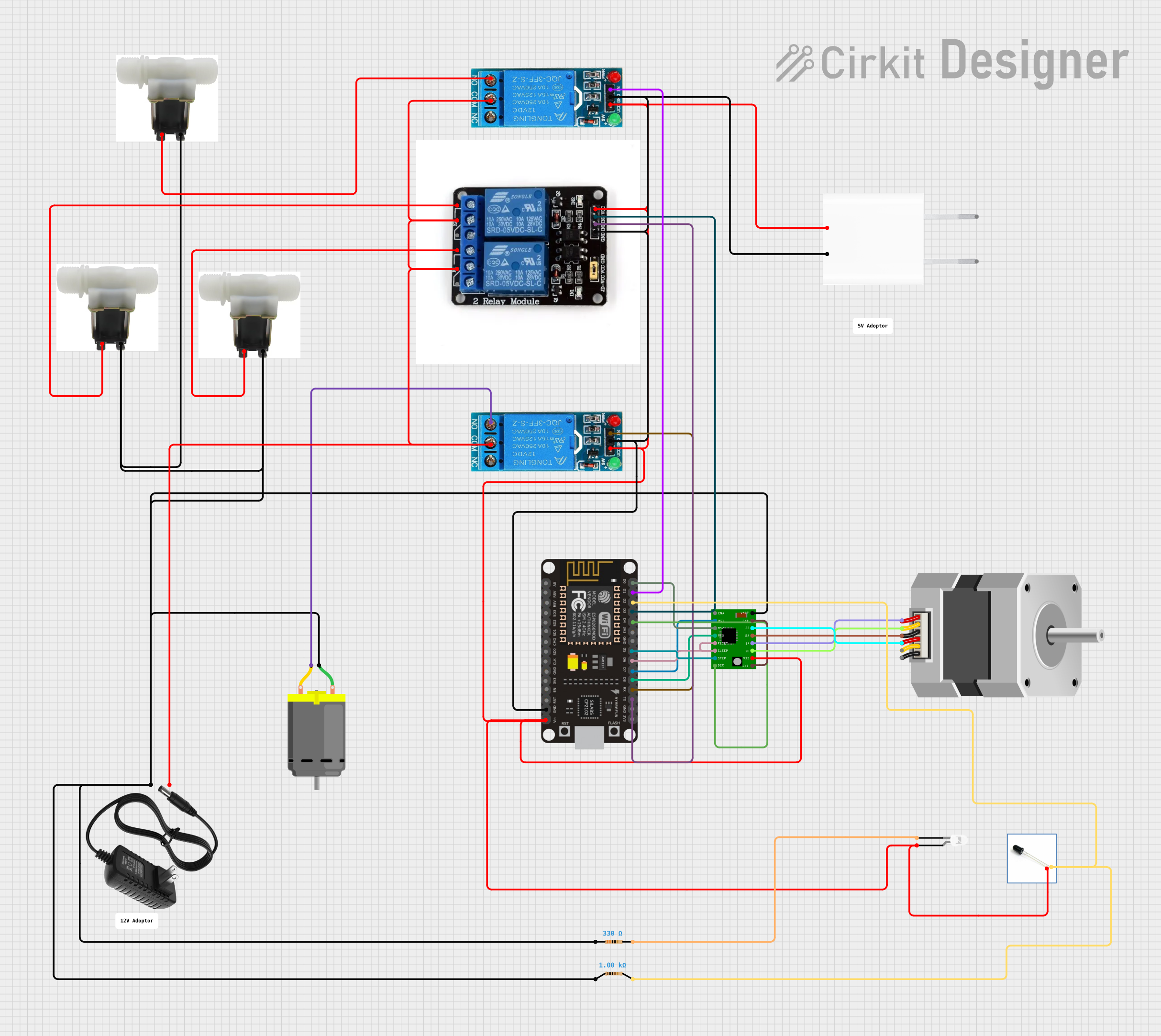
The circuit in question appears to be designed to control a variety of actuators, including water solenoid valves, a DC motor, and a stepper motor, using an ESP8266 NodeMCU microcontroller. The circuit includes power supply components, relay modules for controlling high-power devices, a stepper motor driver, and various discrete components such as resistors and LEDs. The ESP8266 NodeMCU is responsible for interfacing with the actuators and sensors, likely to automate a process or control a system.
Component List
Power Supply Components
- 12v Power Supply: Provides 12V DC power to the circuit.
- 5V Adapter: Converts AC to 5V DC power for low-voltage components.
Actuators
- Water Solenoid Valve: An electrically-controlled valve for controlling the flow of water.
- DC Motor: A motor that runs on DC power.
- Stepper Motor (Unipolar): A type of stepper motor that can be precisely controlled.
Control Modules
- 12V Single Channel Relay: An electromechanical switch that allows a low-power signal to control a high-power circuit.
- Two Channel Relay Module: Similar to the single channel relay but with two independent channels.
Microcontroller
- ESP8266 NodeMCU: A Wi-Fi-enabled microcontroller for controlling the circuit.
Motor Driver
- A4988 Stepper Motor Driver Carrier: A driver module for controlling stepper motors.
Indicators and Sensors
- LED: Two Pin (white): A white light-emitting diode used as an indicator.
- IR Receiver LED: An infrared receiver for remote control or communication.
Discrete Components
- Resistor (330 Ohms): A resistor with a resistance of 330 Ohms.
- Resistor (1000 Ohms): A resistor with a resistance of 1000 Ohms.
Wiring Details
12v Power Supply
- +: Connected to the common (COM) pins of the relay modules and the positive pins of the water solenoid valves.
- -: Connected to the negative pins of the water solenoid valves, the negative pin of the DC motor, and the VMOT pin of the A4988 stepper motor driver.
5V Adapter
- 5V: Powers the VCC pins of the relay modules, the VCC pin of the A4988 stepper motor driver, and the VIN pin of the ESP8266 NodeMCU.
- GND: Common ground for the circuit.
Water Solenoid Valve
- Pos: Connected to the normally open (NO) pin of the corresponding relay module.
- Neg: Connected to the negative side of the power supply.
DC Motor
- Pin 1: Connected to the negative side of the power supply.
- Pin 2: Connected to the normally open (NO) pin of the 12V single channel relay.
Stepper Motor (Unipolar)
- A, B, C, COMMON_1: Connected to the corresponding pins on the A4988 stepper motor driver.
12V Single Channel Relay
- IN: Controlled by the ESP8266 NodeMCU to switch the relay.
- NO: Connected to the positive pin of the water solenoid valve or the pin 2 of the DC motor.
- COM: Connected to the positive side of the power supply.
- GND: Common ground for the circuit.
- VCC: Powered by the 5V adapter.
Two Channel Relay Module
- IN1, IN2: Controlled by the ESP8266 NodeMCU to switch the relays.
- NO: Connected to the positive pins of the water solenoid valves.
- C: Connected to the positive side of the power supply.
- G: Common ground for the circuit.
- VCC: Powered by the 5V adapter.
ESP8266 NodeMCU
- D0-D8, RX, TX: Digital pins used to control the A4988 stepper motor driver and relay modules.
- GND: Common ground for the circuit.
- VIN: Powered by the 5V adapter.
A4988 Stepper Motor Driver Carrier
- MS1, MS2, MS3, DIR, STEP, RESET, SLEEP: Controlled by the ESP8266 NodeMCU for stepper motor operation.
- GND: Common ground for the circuit.
- VCC: Powered by the 5V adapter.
- 1A, 1B, 2A, 2B: Connected to the corresponding pins of the stepper motor.
- VMOT: Connected to the negative side of the power supply.
LED: Two Pin (white)
- Anode: Powered by the 5V adapter.
- Cathode: Connected to a 330 Ohm resistor to limit current.
IR Receiver LED
- Pos: Connected to a 1000 Ohm resistor and controlled by the ESP8266 NodeMCU.
- Neg: Connected to the VCC pin of the 5V adapter.
Resistor (330 Ohms)
- Pin 1: Not connected.
- Pin 2: Connected to the cathode of the white LED.
Resistor (1000 Ohms)
- Pin 1: Connected to the VMOT pin of the A4988 stepper motor driver.
- Pin 2: Connected to the positive pin of the IR Receiver LED and controlled by the ESP8266 NodeMCU.
Documented Code
No code was provided for the ESP8266 NodeMCU or any other programmable components in the circuit. The documentation of the code would typically include descriptions of the functions, control logic, and communication protocols used to interface with the various components of the circuit. Without the code, this section cannot be completed.