
Circuit Documentation
Summary
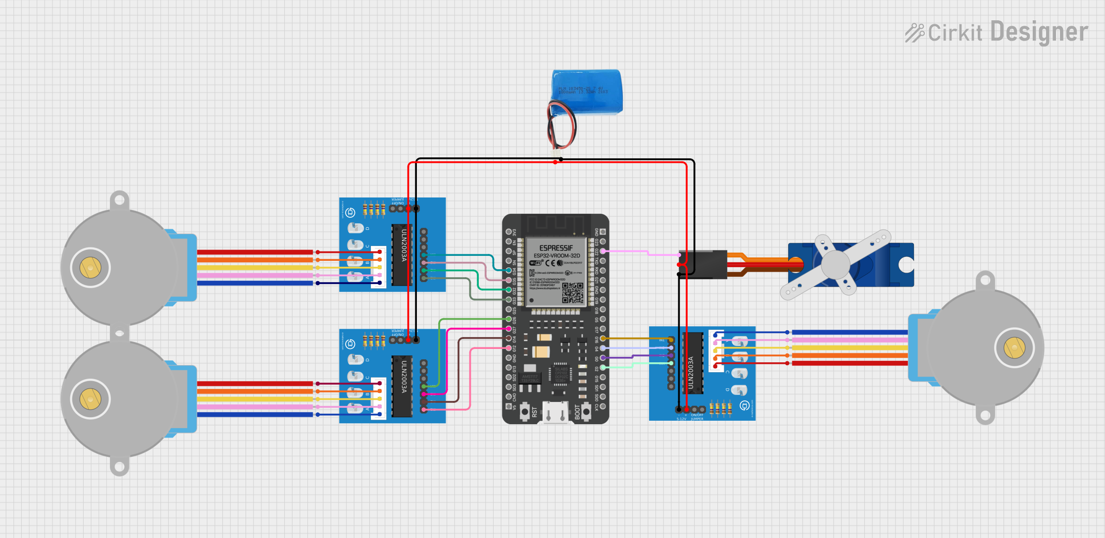
This circuit is designed to control multiple stepper motors and a servo motor using an ESP32 microcontroller. The ESP32 is interfaced with three ULN2003A breakout boards, each of which is connected to a 28BYJ-48 stepper motor. Additionally, the ESP32 controls a Tower Pro SG90 servo motor. The circuit is powered by a 5V battery, which supplies power to the ULN2003A breakout boards and the servo motor.
Component List
ESP32 - 38 pins
- Description: A microcontroller with Wi-Fi and Bluetooth capabilities and a wide range of GPIO pins.
- Pins: 3V3, EN, SP, SN, G34, G35, G32, G33, G25, G26, G27, G14, G12, GND, G13, SD2, SD3, CMD, 5V, G23, G22, TXD, RXD, G21, G19, G18, G5, G17, G16, G4, G0, G2, G15, SD1, SD0, CLK
ULN2003A breakout board
- Description: A breakout board for the ULN2003A Darlington transistor array, used for driving stepper motors.
- Pins: In 1, In 2, In 3, In 4, In 5, In 6, In 7, 0V, +5V, ON/OFF jumper switch, BLUE wire, PINK wire, YELLOW wire, ORANGE wire, RED wire
28BYJ-48 Stepper Motor
- Description: A small, 5-wire unipolar stepper motor.
- Pins: BLUE, PINK, YELLOW, ORANGE, RED
Tower Pro SG90 servo
- Description: A small and lightweight servo motor suitable for RC and robotics applications.
- Pins: Signal, +5V, GND
5V Battery
- Description: A power source for the circuit.
- Pins: positive, negative
Wiring Details
ESP32 - 38 pins
- G34 -> ULN2003A breakout board (In 4)
- G35 -> ULN2003A breakout board (In 3)
- G32 -> ULN2003A breakout board (In 2)
- G33 -> ULN2003A breakout board (In 1)
- G26 -> ULN2003A breakout board (In 4)
- G27 -> ULN2003A breakout board (In 3)
- G14 -> ULN2003A breakout board (In 2)
- G12 -> ULN2003A breakout board (In 1)
- G22 -> Tower Pro SG90 servo (Signal)
- G16 -> ULN2003A breakout board (In 1)
- G4 -> ULN2003A breakout board (In 2)
- G0 -> ULN2003A breakout board (In 3)
- G2 -> ULN2003A breakout board (In 4)
ULN2003A breakout board
- In 1, In 2, In 3, In 4 -> Connected to ESP32 GPIO pins
- 0V -> Common ground with 5V battery and Tower Pro SG90 servo
- +5V -> Connected to the positive terminal of the 5V battery
- BLUE wire, PINK wire, YELLOW wire, ORANGE wire, RED wire -> Connected to corresponding wires of 28BYJ-48 Stepper Motor
28BYJ-48 Stepper Motor
- BLUE, PINK, YELLOW, ORANGE, RED -> Connected to corresponding wires of ULN2003A breakout board
Tower Pro SG90 servo
- Signal -> Connected to ESP32 GPIO pin G22
- +5V -> Connected to the positive terminal of the 5V battery
- GND -> Common ground with 5V battery and ULN2003A breakout boards
5V Battery
- positive -> Connected to +5V on ULN2003A breakout boards and Tower Pro SG90 servo
- negative -> Common ground with ULN2003A breakout boards and Tower Pro SG90 servo
Documented Code
There is no code provided for the microcontrollers in the circuit. The code would typically include the initialization of the GPIO pins on the ESP32 for controlling the stepper motors via the ULN2003A breakout boards and the servo motor. It would also include the logic for the stepping sequence of the stepper motors and the control signals for the servo motor's position.