Cirkit Designer
Your all-in-one circuit design IDE
Home /
Project Documentation
Arduino Mega 2560 Bluetooth-Controlled Flame Detection System with Servo Actuation
Circuit Documentation
Summary
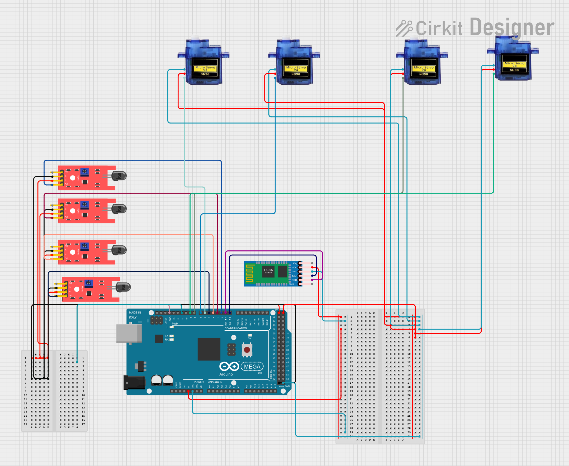
This circuit involves an Arduino Mega 2560 microcontroller interfaced with multiple KY-026 Flame Sensors, HC-05 Bluetooth Module, and Micro Servo 9G motors. The Arduino Mega 2560 serves as the central controller, receiving inputs from the flame sensors and controlling the servos and Bluetooth module.
Component List
Arduino Mega 2560
- Description: A microcontroller board based on the ATmega2560.
- Pins: IOREF, RESET, 3V3, 5V, GND, VIN, A0-A15, D0-D53, PWM pins, AREF, SDA, SCL.
HC-05 Bluetooth Module
- Description: A Bluetooth module for wireless communication.
- Pins: Key, VCC, GND, TXD, RXD, State.
KY-026 Flame Sensor
- Description: A sensor module for detecting flame.
- Pins: A0, GND, VCC, D0.
Micro Servo 9G
- Description: A small servo motor for precise control.
- Pins: GND, +5V, PWM.
Wiring Details
Arduino Mega 2560
- 5V: Connected to VCC of all KY-026 Flame Sensors, VCC of HC-05 Bluetooth Module, and +5V of all Micro Servo 9G motors.
- GND: Connected to GND of all KY-026 Flame Sensors, GND of HC-05 Bluetooth Module, and GND of all Micro Servo 9G motors.
- D0 RX0: Connected to TXD of HC-05 Bluetooth Module.
- D1 TX0: Connected to RXD of HC-05 Bluetooth Module.
- D2 PWM: Connected to D0 of one KY-026 Flame Sensor.
- D3 PWM: Connected to D0 of another KY-026 Flame Sensor.
- D4 PWM: Connected to D0 of another KY-026 Flame Sensor.
- D5 PWM: Connected to D0 of another KY-026 Flame Sensor.
- D6 PWM: Connected to PWM of one Micro Servo 9G motor.
- D7 PWM: Connected to PWM of another Micro Servo 9G motor.
- D8 PWM: Connected to PWM of another Micro Servo 9G motor.
- D9 PWM: Connected to PWM of another Micro Servo 9G motor.
HC-05 Bluetooth Module
- VCC: Connected to 5V of Arduino Mega 2560.
- GND: Connected to GND of Arduino Mega 2560.
- TXD: Connected to D0 RX0 of Arduino Mega 2560.
- RXD: Connected to D1 TX0 of Arduino Mega 2560.
KY-026 Flame Sensor
- VCC: Connected to 5V of Arduino Mega 2560.
- GND: Connected to GND of Arduino Mega 2560.
- D0:
- One sensor's D0 connected to D2 PWM of Arduino Mega 2560.
- Another sensor's D0 connected to D3 PWM of Arduino Mega 2560.
- Another sensor's D0 connected to D4 PWM of Arduino Mega 2560.
- Another sensor's D0 connected to D5 PWM of Arduino Mega 2560.
Micro Servo 9G
- +5V: Connected to 5V of Arduino Mega 2560.
- GND: Connected to GND of Arduino Mega 2560.
- PWM:
- One servo's PWM connected to D6 PWM of Arduino Mega 2560.
- Another servo's PWM connected to D7 PWM of Arduino Mega 2560.
- Another servo's PWM connected to D8 PWM of Arduino Mega 2560.
- Another servo's PWM connected to D9 PWM of Arduino Mega 2560.
Code Documentation
Arduino Mega 2560 Code
sketch.ino
void setup() {
  // put your setup code here, to run once:

}

void loop() {
  // put your main code here, to run repeatedly:

}
documentation.txt
This documentation provides a comprehensive overview of the circuit, including a summary, detailed component list, wiring details, and the code used in the Arduino Mega 2560 microcontroller.