Arduino-Controlled Sequential Solenoid Valve System with Local Override
Circuit Documentation
Summary
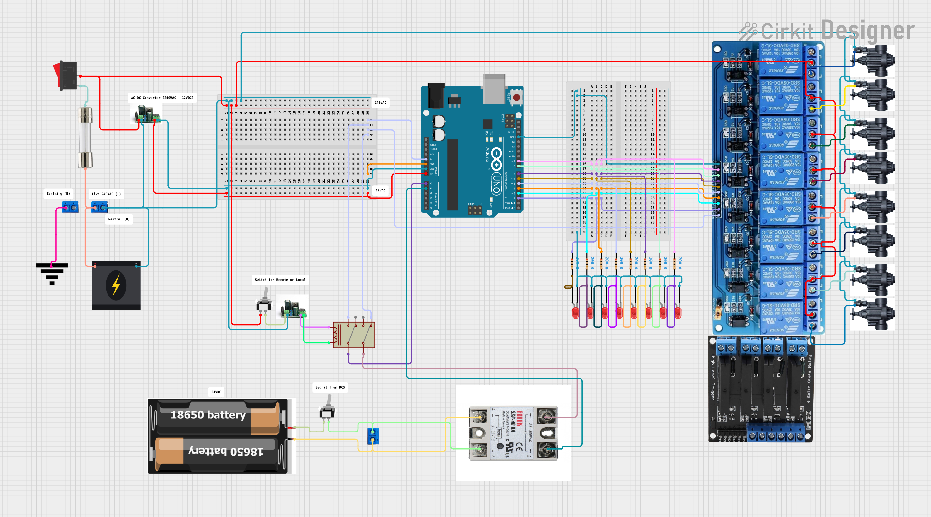
The circuit is designed to control a series of solenoid valves using an Arduino UNO microcontroller. The circuit includes a power supply section that converts 240V AC to a lower voltage suitable for the Arduino and the relays. It features a manual override switch for local control and a set of relays to control the solenoid valves. The Arduino is programmed to operate the valves either in a local control mode or based on serial commands for remote operation.
Component List
Power Supply Components
- 240v Power Source: Supplies the main AC voltage to the circuit.
- Rocker Switch: Acts as a manual on/off switch for the circuit.
- Fuse: Provides overcurrent protection.
- Voltage Converter: Converts the 240V AC supply to a lower DC voltage suitable for the microcontroller and other components.
Control Components
- Arduino UNO: The main microcontroller unit that controls the solenoid valves based on the programmed logic.
- Relay: Electromechanical switches used to control high power devices with low power signals from the microcontroller.
- 5V 8Channel Relay: A relay module with multiple channels to control several devices.
- Solid State Relay: A type of relay that switches on or off when an external voltage is applied across its control terminals.
User Interface Components
- Toggle Switch (SPST): A single-pole single-throw switch used for manual control of the circuit.
- LED (Red): Indicates the status of various parts of the circuit.
- Resistor: Limits the current flowing through the LEDs to prevent damage.
Actuators
- Solenoid Valve (40-01): Electrically controlled valves used for controlling the flow of liquids or gases.
Power Distribution Components
- Terminal PCB 2 Pin: Used for making secure and easy connections between wires and the PCB.
- Power Ground 2: A ground terminal used to provide a common ground reference for the circuit.
Energy Storage
- 2x 18650 Battery: Provides a portable power source for the circuit.
Wiring Details
Power Supply Wiring
- 240v Power Source is connected to the Fuse and Rocker Switch for protection and manual control.
- Voltage Converter is connected to the power source through the switch and converts the AC voltage to a lower DC voltage for the Arduino and relays.
Control Wiring
- Arduino UNO controls the 5V 8Channel Relay module, which in turn controls the Solenoid Valves.
- Solid State Relay is controlled by the Arduino for additional switching capabilities.
User Interface Wiring
- Toggle Switch (SPST) is used for manual control and is wired to the Solid State Relay and Voltage Converter.
- LEDs are connected in series with Resistors to indicate the status and are controlled by the Arduino.
Actuator Wiring
- Solenoid Valves are connected to the 5V 8Channel Relay module and are operated based on the control signals from the Arduino.
Power Distribution Wiring
- Terminal PCB 2 Pin is used to distribute power from the Voltage Converter to the Arduino and other components.
- Power Ground 2 provides a common ground reference for the circuit.
Energy Storage Wiring
- 2x 18650 Battery is connected to the Solid State Relay to provide a backup power source.
Documented Code
// Arduino UNO Code
const int solenoidValves[10] = {2, 3, 4, 5, 6, 7, 8, 9, 10, 11}; // Relay control pins
const int localControlPin = 12; // Local control switch pin
const unsigned long timerDuration = 5000; // 5 seconds in milliseconds
bool localControl = false;
int startValve = 0; // 0 for valve 1, 1 for valve 2, 2 for valve 3, etc.

void setup() {
  Serial.begin(9600); // Start serial communication for DCS signals
  pinMode(localControlPin, INPUT_PULLUP); // Local control switch with pull-up resistor

  for (int i = 0; i < 10; i++) {
    pinMode(solenoidValves[i], OUTPUT);
    digitalWrite(solenoidValves[i], LOW); // Ensure valves are off initially
  }
}

void loop() {
  if (digitalRead(localControlPin) == LOW) {
    localControl = !localControl; // Toggle local control mode
    delay(200); // Debounce delay
  }

  if (localControl) {
    // Local control logic
    // Implement the logic for local control here
    // For example, you might want to manually turn on/off valves
  } else {
    // Remote control logic
    if (Serial.available() > 0) {
      char command = Serial.read();
      if (command == '2') {
        startValve = 1; // Start from solenoid valve number 2
      } else if (command == '3') {
        startValve = 2; // Start from solenoid valve number 3
      }
    }

    // Operate the solenoid valves with a 5-second delay between each
    for (int i = startValve; i < startValve + 10; i++) {
      int valveIndex = i % 10; // Wrap around to the beginning of the array
      digitalWrite(solenoidValves[valveIndex], HIGH); // Turn on valve
      delay(timerDuration); // Wait for 5 seconds
      digitalWrite(solenoidValves[valveIndex], LOW); // Turn off valve
    }
  }
}
This code is designed to control a series of solenoid valves using an Arduino UNO. It includes a local control mode that can be toggled via a switch and a remote control mode that operates based on serial commands. The valves are operated with a 5-second delay between each, and the starting valve can be adjusted via serial commands.