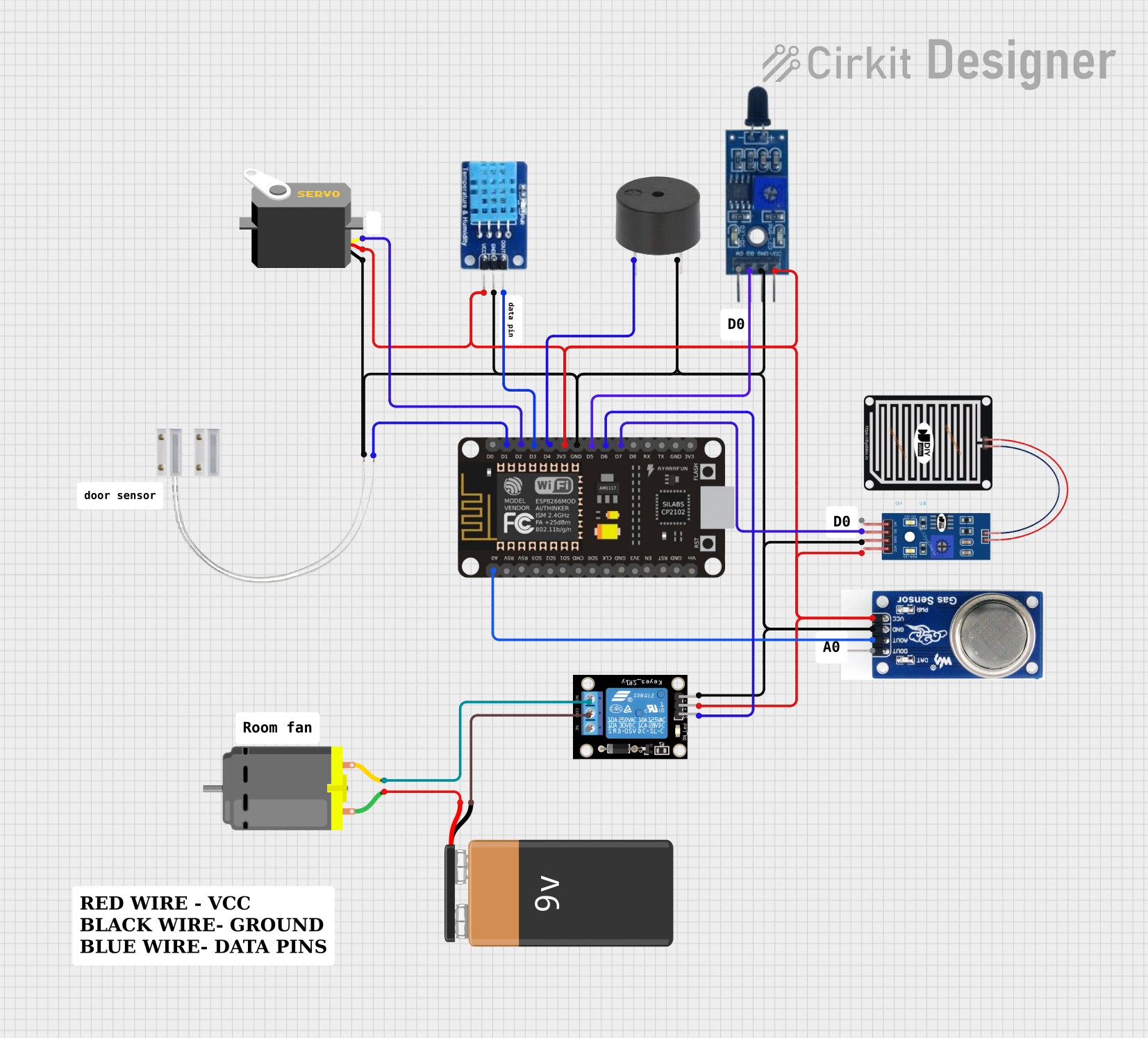
ESP8266 NodeMCU-Based Multi-Sensor Monitoring and Actuation System

Circuit Documentation
Summary
The circuit in question is designed to interface various sensors and actuators with an ESP8266 NodeMCU microcontroller. The circuit includes environmental sensors, a servo motor, a DC motor, a relay module for controlling high-power devices, and a buzzer for audio signaling. The ESP8266 NodeMCU is the central processing unit of the circuit, programmed to interact with the connected devices based on the sensor inputs and predefined logic.
Component List
RAIN SENSOR
- Pins: AO (Analog Output), DO (Digital Output), GRD (Ground), VCC (Power Supply)
- Description: Detects rain by measuring raindrop-induced changes in resistance.
Servo
- Pins: gnd (Ground), vcc (Power Supply), pulse (Control Signal)
- Description: A motor capable of precise position control.
9V Battery
- Pins: - (Negative), + (Positive)
- Description: Provides power to the circuit.
DC Motor
- Pins: pin 1, pin 2
- Description: Converts electrical energy into mechanical rotation.
ESP8266 NodeMCU
- Pins: D0-D8, RX, TX, A0, RSV, SD3, SD2, SD1, CMD, SD0, CLK, EN, RST, VIN, 3V3, GND
- Description: A microcontroller with Wi-Fi capabilities for controlling and monitoring devices.
DHT11
- Pins: DATA, GND, VCC
- Description: Measures ambient temperature and humidity.
MQ2
- Pins: D0 (Digital Output), A0 (Analog Output), GND, VCC
- Description: Gas sensor for detecting LPG, propane, hydrogen, and other gases.
Flame Sensor
- Pins: VCC, GND, D0 (Digital Output), A0 (Analog Output)
- Description: Detects the presence of a flame or fire.
Buzzer
- Pins: PIN, GND
- Description: Emits an audible alert when activated.
Relay Module 1 Channel
- Pins: S (Signal), 5V, GND, NC (Normally Closed), COM (Common), NO (Normally Open)
- Description: Electrically operated switch that allows control of a high voltage circuit with a low voltage signal.
Door MC-38
- Pins: S (Signal), GND
- Description: Magnetic switch that detects door/window open or close status.
Wiring Details
RAIN SENSOR
- VCC: Connected to 3V3 power supply net.
- GRD: Connected to ground net.
- AO: Not connected.
- DO: Connected to ESP8266 NodeMCU pin D7.
Servo
- vcc: Connected to 3V3 power supply net.
- gnd: Connected to ground net.
- pulse: Connected to ESP8266 NodeMCU pin D2.
DC Motor
- pin 1: Connected to 9V Battery positive.
- pin 2: Connected to Relay Module 1 Channel NO.
ESP8266 NodeMCU
- D1: Connected to Door MC-38 S.
- D2: Connected to Servo pulse.
- D3: Connected to DHT11 DATA.
- D4: Connected to Buzzer PIN.
- D5: Connected to Flame Sensor D0.
- D6: Connected to Relay Module 1 Channel S.
- D7: Connected to RAIN SENSOR DO.
- A0: Connected to MQ2 A0.
- 3V3: Connected to 3V3 power supply net.
- GND: Connected to ground net.
DHT11
- VCC: Connected to 3V3 power supply net.
- GND: Connected to ground net.
- DATA: Connected to ESP8266 NodeMCU pin D3.
MQ2
- VCC: Connected to 3V3 power supply net.
- GND: Connected to ground net.
- A0: Connected to ESP8266 NodeMCU pin A0.
- D0: Not connected.
Flame Sensor
- VCC: Connected to 3V3 power supply net.
- GND: Connected to ground net.
- D0: Connected to ESP8266 NodeMCU pin D5.
- A0: Not connected.
Buzzer
- PIN: Connected to ESP8266 NodeMCU pin D4.
- GND: Connected to ground net.
Relay Module 1 Channel
- S: Connected to ESP8266 NodeMCU pin D6.
- 5V: Connected to 3V3 power supply net.
- GND: Connected to ground net.
- NC: Not connected.
- COM: Connected to 9V Battery negative.
- NO: Connected to DC Motor pin 2.
Door MC-38
- S: Connected to ESP8266 NodeMCU pin D1.
- GND: Connected to ground net.
Documented Code
sketch.ino
void setup() {
  // put your setup code here, to run once:

}

void loop() {
  // put your main code here, to run repeatedly:

}
documentation.txt
The code for the ESP8266 NodeMCU is currently a template with empty setup and loop functions. The setup function is intended for initialization code that runs once, while the loop function contains code that runs repeatedly. The user is expected to fill in these functions with the logic required to read sensor data, control actuators, and communicate with other devices or services as needed.