
Arduino UNO-Based Automated Testing System with Relays and Sensors
View and Edit Project In Cirkit Designer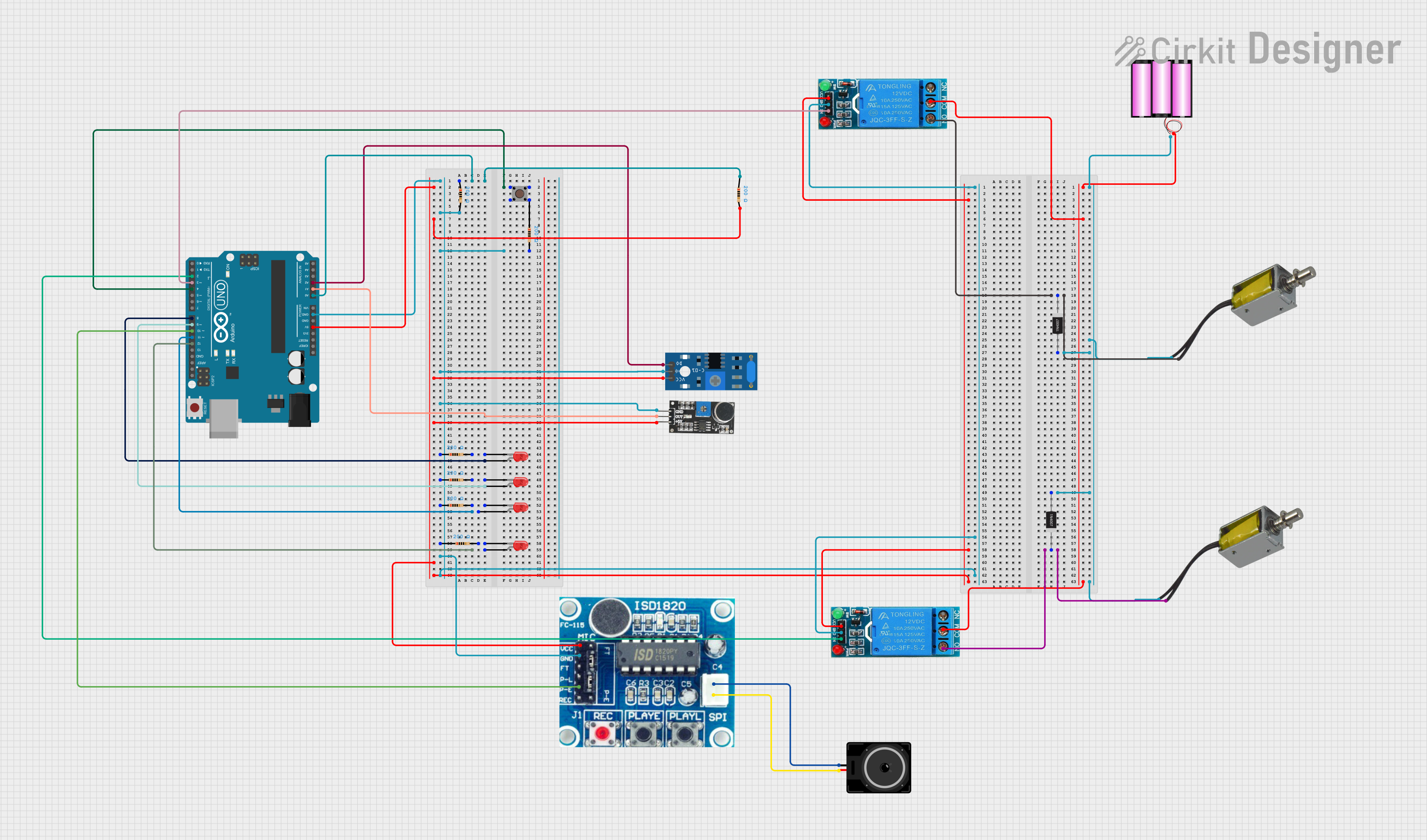
Circuit Documentation
Summary
This circuit is designed to perform a series of tests using various sensors and actuators controlled by an Arduino UNO. The tests include light detection, vibration detection, loopback audio test, and melody detection. The results of these tests are indicated using LEDs and solenoids, and the circuit also includes a sound playback module.
Component List
12V SINGLE CHANNEL RELAY
- Pins: NC, COM, NO, IN, GND, VCC
- Description: A relay module used to control high voltage devices with a low voltage signal.
Push Pull Solenoid
- Pins: +ve, -ve
- Description: An actuator that provides linear motion when powered.
Battery 12V
- Pins: +, -
- Description: A 12V power source for the circuit.
Arduino UNO
- Pins: UNUSED, IOREF, Reset, 3.3V, 5V, GND, Vin, A0, A1, A2, A3, A4, A5, SCL, SDA, AREF, D13, D12, D11, D10, D9, D8, D7, D6, D5, D4, D3, D2, D1, D0
- Description: A microcontroller board used to control the circuit.
1N4007 Rectifier Diode
- Pins: Cathode, Anode
- Description: A diode used to allow current to flow in one direction only.
LED: Two Pin (red)
- Pins: cathode, anode
- Description: A red LED used for visual indication.
Resistor
- Pins: pin1, pin2
- Description: A resistor with a resistance of 200 Ohms.
ISD1820
- Pins: VCC, GND, P-E, Sp1, SP2
- Description: A sound playback module.
Loudspeaker
- Pins: pin1, pin2
- Description: A speaker used to output sound.
Sound Sensor
- Pins: 5V +, OUT, GND
- Description: A sensor used to detect sound levels.
SW-420 Vibration Sensor
- Pins: vcc, Ground, Digital output
- Description: A sensor used to detect vibrations.
Pushbutton
- Pins: Pin 3 (out), Pin 4 (out), Pin 1 (in), Pin 2 (in)
- Description: A button used to trigger the tests.
Wiring Details
12V SINGLE CHANNEL RELAY
- NO: Connected to the +ve pin of the Push Pull Solenoid.
- COM: Connected to the + pin of the Battery 12V.
- GND: Connected to the GND pin of the Arduino UNO.
- VCC: Connected to the 5V pin of the Arduino UNO.
- IN: Connected to the D3 pin of the Arduino UNO.
Push Pull Solenoid
- +ve: Connected to the NO pin of the 12V SINGLE CHANNEL RELAY.
- -ve: Connected to the - pin of the Battery 12V.
Battery 12V
- +: Connected to the COM pin of the 12V SINGLE CHANNEL RELAY.
- -: Connected to the Anode pin of the 1N4007 Rectifier Diode.
Arduino UNO
- A0: Connected to pin1 of the Resistor.
- A1: Connected to the OUT pin of the Sound Sensor.
- A2: Connected to the Digital output pin of the SW-420 Vibration Sensor.
- D2: Connected to the IN pin of the 12V SINGLE CHANNEL RELAY.
- D3: Connected to the IN pin of the 12V SINGLE CHANNEL RELAY.
- D4: Connected to Pin 1 (in) and Pin 2 (in) of the Pushbutton.
- D8: Connected to the anode pin of the LED: Two Pin (red).
- D9: Connected to the anode pin of the LED: Two Pin (red).
- D10: Connected to the P-E pin of the ISD1820.
- D11: Connected to the anode pin of the LED: Two Pin (red).
- D12: Connected to the anode pin of the LED: Two Pin (red).
- GND: Connected to pin2 of the Resistor, Ground pin of the SW-420 Vibration Sensor, GND pin of the Sound Sensor, GND pin of the ISD1820, and GND pin of the 12V SINGLE CHANNEL RELAY.
1N4007 Rectifier Diode
- Cathode: Connected to the +ve pin of the Push Pull Solenoid.
- Anode: Connected to the - pin of the Battery 12V.
LED: Two Pin (red)
- anode: Connected to the D8, D9, D11, and D12 pins of the Arduino UNO.
- cathode: Connected to pin2 of the Resistor.
Resistor
- pin1: Connected to pin1 of another Resistor and A0 pin of the Arduino UNO.
- pin2: Connected to pin2 of another Resistor and GND pin of the Arduino UNO.
ISD1820
- VCC: Connected to the 5V pin of the Arduino UNO.
- GND: Connected to the GND pin of the Arduino UNO.
- P-E: Connected to the D10 pin of the Arduino UNO.
- Sp1: Connected to pin1 of the Loudspeaker.
- SP2: Connected to pin2 of the Loudspeaker.
Loudspeaker
- pin1: Connected to the Sp1 pin of the ISD1820.
- pin2: Connected to the SP2 pin of the ISD1820.
Sound Sensor
- 5V +: Connected to the 5V pin of the Arduino UNO.
- OUT: Connected to the A1 pin of the Arduino UNO.
- GND: Connected to the GND pin of the Arduino UNO.
SW-420 Vibration Sensor
- vcc: Connected to the 5V pin of the Arduino UNO.
- Ground: Connected to the GND pin of the Arduino UNO.
- Digital output: Connected to the A2 pin of the Arduino UNO.
Pushbutton
- Pin 1 (in): Connected to the D4 pin of the Arduino UNO.
- Pin 2 (in): Connected to the D4 pin of the Arduino UNO.
- Pin 3 (out): Connected to Pin 4 (out) of the Pushbutton.
- Pin 4 (out): Connected to pin1 of the Resistor.
Code Documentation
// Pin definitions
const int vibrationSensorPin = A2;
const int soundAnalogPin = A1;  // Analog output from sound sensor
const int lightAnalogPin = A0;  // Analog input from photoresistor
const int Light_ledPin = 8;     // LED connected to digital pin 9
const int Vibration_ledPin = 9;
const int Loopback_ledPin = 11;
const int Melody_ledPin = 12;
const int isdPlayPin = 10;      // ISD1820 playback pin connected to digital pin 10
const int buttonPin = 4;        // Button to trigger the loop

// Relay pins for solenoids (pass and fail)
const int relayPassPin = 2;   // Relay for solenoid (test passed)
const int relayFailPin = 3;   // Relay for solenoid (test failed)

bool buttonPressed = false;    // Flag to check if button is pressed
bool buttonState = HIGH;       // Current state of the button (not pressed)
bool lastButtonState = HIGH;   // Previous state of the button
bool runTest = false;          // Flag to run the loop

void setup() {
  // Initialize serial communication
  Serial.begin(9600);

  // Set the LED, ISD1820 playback, and button pins as output/input
  pinMode(Light_ledPin , OUTPUT);
  pinMode(Vibration_ledPin , OUTPUT);
  pinMode(Loopback_ledPin , OUTPUT);
  pinMode(Melody_ledPin , OUTPUT);
  pinMode(isdPlayPin, OUTPUT);    // ISD1820 playback pin
  pinMode(vibrationSensorPin, INPUT);
  pinMode(buttonPin, INPUT_PULLUP); // Use internal pull-up resistor for the button

  // Set relay pins as output
  pinMode(relayPassPin, OUTPUT);
  pinMode(relayFailPin, OUTPUT);

  // Turn off the LEDs and ISD1820 playback initially
  digitalWrite(Light_ledPin, LOW);
  digitalWrite(Vibration_ledPin, LOW);
  digitalWrite(Loopback_ledPin, LOW);
  digitalWrite(Melody_ledPin, LOW);