
Arduino UNO Controlled Quadcopter with GPS, Ultrasonic Sensing, and Wireless Communication
View and Edit Project In Cirkit Designer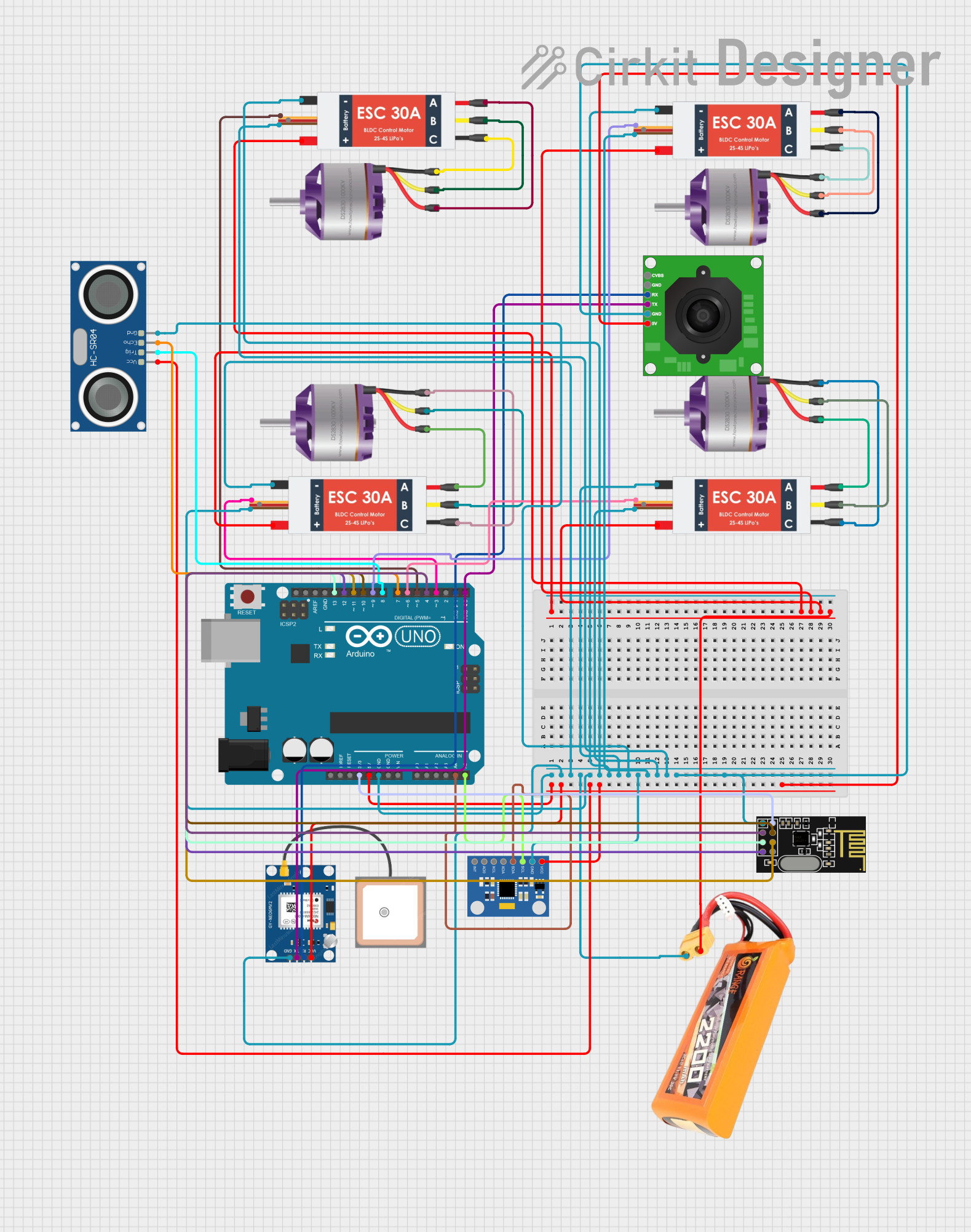
Circuit Documentation
Summary
This circuit integrates various components to form a complex system, likely designed for a remote-controlled vehicle or drone with telemetry capabilities. It includes an Arduino UNO as the central microcontroller, interfacing with a GPS module, ultrasonic sensor, accelerometer and gyroscope module, a TTL serial JPEG camera, an NRF24L01 wireless module, and four brushless motors each with its own electronic speed controller (ESC). A lipo battery provides power to the system.
Component List
Microcontroller
- Arduino UNO: A microcontroller board based on the ATmega328P, featuring digital and analog I/O pins.
Sensors and Modules
- GPS NEO 6M: A GPS module for satellite navigation.
- HC-SR04 Ultrasonic Sensor: An ultrasonic sensor used for measuring distances via sonar.
- MPU6050 Accelerometer + Gyroscope (Wokwi Compatible): A sensor for measuring acceleration and rotational rates.
- TTL Serial JPEG Camera: A camera module capable of capturing and transmitting JPEG images.
- NRF24L01: A wireless communication module for short-range RF communication.
Actuators
- Brushless Motor: An electric motor that is part of a brushless motor system.
Power Management
- Electronic Speed Controller (ESC): A device that regulates the speed and direction of a brushless motor.
- Lipo battery 2200mAH 30c: A rechargeable battery that provides power to the circuit.
Wiring Details
Arduino UNO
- 5V: Powers the GPS NEO 6M, HC-SR04 Ultrasonic Sensor, MPU6050, and TTL Serial JPEG Camera.
- GND: Common ground for the entire circuit.
- 3.3V: Powers the NRF24L01 module.
- A4 (SDA): Data line for I2C communication with the MPU6050.
- A5 (SCL): Clock line for I2C communication with the MPU6050.
- D0-D13: Digital pins used for various signal controls and communication with other modules.
GPS NEO 6M
- VCC: Powered by the Arduino UNO's 5V output.
- RX: Receives data from the TTL Serial JPEG Camera's TX pin.
- TX: Transmits data to the Arduino UNO's D0 pin.
HC-SR04 Ultrasonic Sensor
- VCC: Powered by the Arduino UNO's 5V output.
- TRIG: Trigger pin connected to Arduino UNO's D8 pin.
- ECHO: Echo pin connected to Arduino UNO's D7 pin.
MPU6050 Accelerometer + Gyroscope
- VCC: Powered by the Arduino UNO's 5V output.
- GND: Connected to the common ground.
- SDA: Connected to Arduino UNO's A4 pin.
- SCL: Connected to Arduino UNO's A5 pin.
TTL Serial JPEG Camera
- 5V: Powered by the Arduino UNO's 5V output.
- RX: Receives data from the Arduino UNO's D0 pin.
- TX: Transmits data to the GPS NEO 6M's RX pin.
NRF24L01
- VCC (3V): Powered by the Arduino UNO's 3.3V output.
- CE: Connected to Arduino UNO's D4 pin.
- CSN: Connected to Arduino UNO's D10 pin.
- SCK: Connected to Arduino UNO's D13 pin.
- MOSI: Connected to Arduino UNO's D11 pin.
- MISO: Connected to Arduino UNO's D12 pin.
Brushless Motors
- L1, L2, L3: Connected to the corresponding M1, M2, M3 pins on their respective ESCs.
Electronic Speed Controllers (ESCs)
- Battery VCC: All connected to the lipo battery's VCC.
- Battery GND: All connected to the lipo battery's GND and the common ground.
- Signal: Connected to various digital pins on the Arduino UNO (D3, D5, D6, D9) for speed control signals.
Lipo Battery 2200mAH 30c
- VCC: Provides power to all four ESCs.
- GND: Common ground for the entire circuit.
Documented Code
Arduino UNO Code (sketch.ino)
void setup() {
  // put your setup code here, to run once:

}

void loop() {
  // put your main code here, to run repeatedly:

}
This code is a template and does not contain any functional implementation. It is expected that the user will fill in the setup() and loop() functions with the necessary initialization and main operational code for the circuit's intended functionality.