
Arduino UNO-Based Smart Monitoring System with GSM and LCD Display
View and Edit Project In Cirkit Designer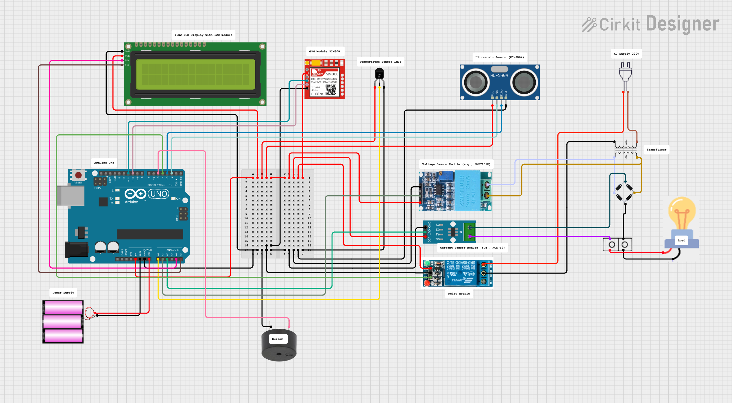
Circuit Documentation
Summary
This circuit is designed to monitor temperature, voltage, current, and oil level, and to control a relay and a buzzer based on threshold values. It uses an Arduino UNO as the main microcontroller, interfacing with various sensors and actuators. The system also includes a GSM module for sending SMS alerts in case of faults.
Component List
HC-SR04 Ultrasonic Sensor
- Pins: VCC, TRIG, ECHO, GND
- Description: Measures distance using ultrasonic waves.
- Purpose: Used to measure oil level.
ACS712 Current Sensor 5A 20A 30A
- Pins: 1, 2, GND, OUT, VCC
- Description: Measures current.
- Purpose: Used to measure current in the circuit.
Sim800l
- Pins: NET, RST, VCC, RXD, TXD, GND
- Description: GSM module for sending SMS.
- Purpose: Sends SMS alerts in case of faults.
5v Relay
- Pins: Normally Open, Common terminal, Normally Closed, In, GND, VCC
- Description: Electromechanical switch.
- Purpose: Controls the power to the transformer.
16x2 I2C LCD
- Pins: GND, VCC, SDA, SCL
- Description: LCD display with I2C interface.
- Purpose: Displays sensor readings and system status.
Battery 12v
- Pins: +, -
- Description: Power source.
- Purpose: Provides power to the Arduino UNO.
Temperature Sensor (LM35)
- Pins: +Vs, Vout, GND
- Description: Measures temperature.
- Purpose: Used to measure temperature.
Arduino UNO
- Pins: UNUSED, IOREF, Reset, 3.3V, 5V, GND, Vin, A0, A1, A2, A3, A4, A5, SCL, SDA, AREF, D13, D12, D11, D10, D9, D8, D7, D6, D5, D4, D3, D2, D1, D0
- Description: Microcontroller board.
- Purpose: Main controller for the circuit.
Power 220v
- Pins: hot wire, neutral wire
- Description: AC power source.
- Purpose: Provides AC power to the transformer.
Power Transformer (220V to 24V)
- Pins: 2 - Primary, 1 - Primary, 3 - Secondary, 4 - Secondary
- Description: Steps down 220V AC to 24V AC.
- Purpose: Provides 24V AC for the circuit.
Bulb
- Pins: GND, power
- Description: Light bulb.
- Purpose: Visual indicator.
Bridge Rectifier
- Pins: Source_in-, source_out-, source_out+, source_in+
- Description: Converts AC to DC.
- Purpose: Provides DC power from AC source.
Wire Connector
- Pins: +, -
- Description: Connects wires.
- Purpose: Facilitates connections in the circuit.
ZMPT101B
- Pins: OUT, GND, VCC, NEUTRO, FASE
- Description: Voltage sensor.
- Purpose: Measures voltage in the circuit.
Buzzer
- Pins: PIN, GND
- Description: Sound indicator.
- Purpose: Alerts in case of faults.
Wiring Details
HC-SR04 Ultrasonic Sensor
- VCC: Connected to Arduino UNO 5V
- TRIG: Connected to Arduino UNO D2
- ECHO: Connected to Arduino UNO D3
- GND: Connected to common ground
ACS712 Current Sensor 5A 20A 30A
- 1: Connected to wire connector (-)
- 2: Connected to Bridge rectifier source_out+
- GND: Connected to common ground
- OUT: Connected to Arduino UNO A2
- VCC: Connected to Arduino UNO 5V
Sim800l
- VCC: Connected to Arduino UNO 5V
- RXD: Connected to Arduino UNO D11
- TXD: Connected to Arduino UNO D10
- GND: Connected to common ground
5v Relay
- VCC: Connected to Arduino UNO 5V
- In: Connected to Arduino UNO D4
- GND: Connected to common ground
- Common terminal: Connected to Power Transformer (220V to 24V) 2 - Primary
- Normally Closed: Connected to power 220v hot wire
16x2 I2C LCD
- GND: Connected to common ground
- VCC: Connected to Arduino UNO 5V
- SDA: Connected to Arduino UNO A4
- SCL: Connected to Arduino UNO A5
Battery 12v
- +: Connected to Arduino UNO Vin
- -: Connected to Arduino UNO GND
Temperature Sensor (LM35)
- +Vs: Connected to Arduino UNO 5V
- Vout: Connected to Arduino UNO A0
- GND: Connected to common ground
Arduino UNO
- 5V: Connected to common 5V line
- GND: Connected to common ground
- Vin: Connected to Battery 12v +
- A0: Connected to Temperature Sensor (LM35) Vout
- A1: Connected to ZMPT101B OUT
- A2: Connected to ACS712 Current Sensor 5A 20A 30A OUT
- A4: Connected to 16x2 I2C LCD SDA
- A5: Connected to 16x2 I2C LCD SCL
- D2: Connected to HC-SR04 Ultrasonic Sensor TRIG
- D3: Connected to HC-SR04 Ultrasonic Sensor ECHO
- D4: Connected to 5v Relay In
- D5: Connected to Buzzer PIN
- D10: Connected to Sim800l TXD
- D11: Connected to Sim800l RXD
Power 220v
- hot wire: Connected to 5v Relay Normally Closed
- neutral wire: Connected to Power Transformer (220V to 24V) 1 - Primary
Power Transformer (220V to 24V)
- 2 - Primary: Connected to 5v Relay Common terminal
- 1 - Primary: Connected to power 220v neutral wire
- 3 - Secondary: Connected to Bridge rectifier source_in+
- 4 - Secondary: Connected to Bridge rectifier Source_in-
Bulb
- GND: Connected to wire connector +
- power: Connected to wire connector -
Bridge Rectifier
- Source_in+: Connected to Power Transformer (220V to 24V) 3 - Secondary
- Source_in-: Connected to Power Transformer (220V to 24V) 4 - Secondary
- source_out+: Connected to ACS712 Current Sensor 5A 20A 30A 2
- source_out-: Connected to wire connector +
Wire Connector
- +: Connected to Bridge rectifier source_out-
- -: Connected to ACS712 Current Sensor 5A 20A 30A 1
ZMPT101B
- OUT: Connected to Arduino UNO A1
- GND: Connected to common ground
- VCC: Connected to Arduino UNO 5V
- NEUTRO: Connected to Power Transformer (220V to 24V) 3 - Secondary
- FASE: Connected to Power Transformer (220V to 24V) 4 - Secondary
Buzzer
- PIN: Connected to Arduino UNO D5
- GND: Connected to common ground
Code Documentation
#include <LiquidCrystal_I2C.h>
#include <SoftwareSerial.h>

LiquidCrystal_I2C lcd(0x27, 16, 2); // LCD address, columns, rows
SoftwareSerial gsm(10, 11); // TX, RX for GSM

// Sensor pins
const int tempPin = A0;
const int voltagePin = A1;
const int currentPin = A2;
const int trigPin = 2;
const int echoPin = 3;

// Actuator pins
const int relayPin = 4;
const int buzzerPin = 5;

// Thresholds
const float tempThreshold = 50.0; // Celsius
const float voltageThreshold = 230.0; // Volts

void setup() {
  pinMode(relayPin, OUTPUT);
  pinMode(buzzerPin, OUTPUT);
  digitalWrite(relayPin, HIGH); // Default: Relay