
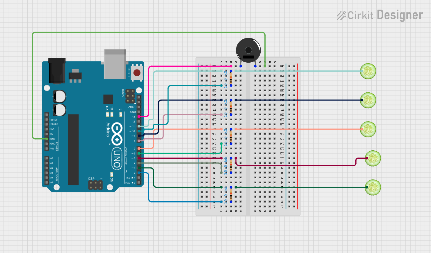
Circuit Documentation
Summary
This circuit utilizes an Arduino UNO microcontroller to read capacitive sensor inputs and produce corresponding tones through a piezo buzzer. The capacitive sensors are created using resistors and cucumbers, which act as touch-sensitive elements. When a cucumber is touched, the corresponding sensor value increases, and the Arduino generates a tone on the piezo buzzer.
Component List
Arduino UNO
- Description: A microcontroller board based on the ATmega328P.
- Pins: UNUSED, IOREF, Reset, 3.3V, 5V, GND, Vin, A0, A1, A2, A3, A4, A5, SCL, SDA, AREF, D13, D12, D11, D10, D9, D8, D7, D6, D5, D4, D3, D2, D1, D0
Resistor
- Description: A passive electrical component with a resistance of 10k Ohms.
- Pins: pin1, pin2
- Properties:
- Resistance: 10k Ohms
Cucumber
- Description: A touch-sensitive element used in the capacitive sensor.
- Pins: 1
Piezo Buzzer
- Description: An audio signaling device.
- Pins: pin 1, pin 2
Wiring Details
Arduino UNO
- D2: Connected to pin1 of a 10k Ohm resistor.
- D3: Connected to pin2 of the same 10k Ohm resistor and pin 1 of a cucumber.
- D4: Connected to pin1 of another 10k Ohm resistor.
- D5: Connected to pin2 of the same 10k Ohm resistor and pin 1 of another cucumber.
- D6: Connected to pin1 of another 10k Ohm resistor.
- D7: Connected to pin2 of the same 10k Ohm resistor and pin 1 of another cucumber.
- D8: Connected to pin1 of another 10k Ohm resistor.
- D9: Connected to pin2 of the same 10k Ohm resistor and pin 1 of another cucumber.
- D10: Connected to pin1 of another 10k Ohm resistor.
- D11: Connected to pin2 of the same 10k Ohm resistor and pin 1 of another cucumber.
- D13: Connected to pin 1 of the piezo buzzer.
- GND: Connected to pin 2 of the piezo buzzer.
Resistor
10k Ohm Resistor 1
- pin1: Connected to D2 of Arduino UNO.
- pin2: Connected to D3 of Arduino UNO and pin 1 of a cucumber.
10k Ohm Resistor 2
- pin1: Connected to D4 of Arduino UNO.
- pin2: Connected to D5 of Arduino UNO and pin 1 of another cucumber.
10k Ohm Resistor 3
- pin1: Connected to D6 of Arduino UNO.
- pin2: Connected to D7 of Arduino UNO and pin 1 of another cucumber.
10k Ohm Resistor 4
- pin1: Connected to D8 of Arduino UNO.
- pin2: Connected to D9 of Arduino UNO and pin 1 of another cucumber.
10k Ohm Resistor 5
- pin1: Connected to D10 of Arduino UNO.
- pin2: Connected to D11 of Arduino UNO and pin 1 of another cucumber.
Cucumber
Cucumber 1
- pin 1: Connected to pin2 of a 10k Ohm resistor and D3 of Arduino UNO.
Cucumber 2
- pin 1: Connected to pin2 of another 10k Ohm resistor and D5 of Arduino UNO.
Cucumber 3
- pin 1: Connected to pin2 of another 10k Ohm resistor and D7 of Arduino UNO.
Cucumber 4
- pin 1: Connected to pin2 of another 10k Ohm resistor and D9 of Arduino UNO.
Cucumber 5
- pin 1: Connected to pin2 of another 10k Ohm resistor and D11 of Arduino UNO.
Piezo Buzzer
- pin 1: Connected to D13 of Arduino UNO.
- pin 2: Connected to GND of Arduino UNO.
Documented Code
#include <CapacitiveSensor.h>

CapacitiveSensor a = CapacitiveSensor(2,3);
CapacitiveSensor b = CapacitiveSensor(4,5);
CapacitiveSensor c = CapacitiveSensor(6,7);
CapacitiveSensor d = CapacitiveSensor(8,9);
CapacitiveSensor e = CapacitiveSensor(10,11);

void setup() {
  // put your setup code here, to run once:
  Serial.begin(9600);
}

void loop() {
  // put your main code here, to run repeatedly:
  long SEN1 = a.capacitiveSensorRaw(30);
  long SEN2 = b.capacitiveSensorRaw(30);
  long SEN3 = c.capacitiveSensorRaw(30);
  long SEN4 = d.capacitiveSensorRaw(30);
  long SEN5 = e.capacitiveSensorRaw(30);

  if (SEN1 > 10)
  {
    tone(13, 262, 100);
  }

  if (SEN2 > 10)
  {
    tone(13, 294, 100);
  }

  if (SEN3 > 10)
  {
    tone(13, 330, 100);
  }

  if (SEN4 > 10)
  {
    tone(13, 349, 100);
  }

  if (SEN5 > 10)
  {
    tone(13, 392, 100);
  }
}
This code initializes five capacitive sensors connected to the Arduino UNO. In the setup function, the serial communication is started. In the loop function, the raw sensor values are read, and if any sensor value exceeds a threshold of 10, a corresponding tone is generated on the piezo buzzer.