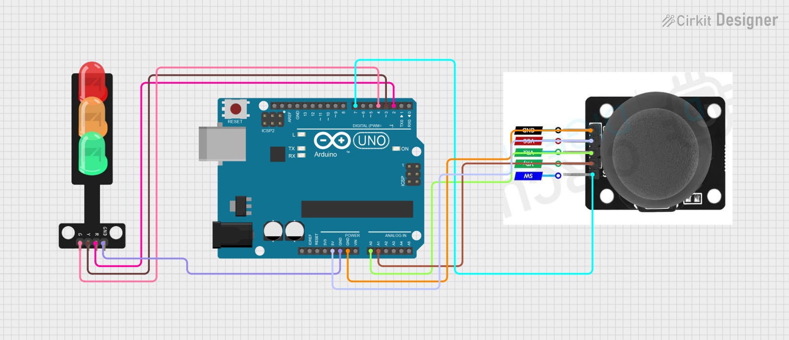
Arduino-Controlled Traffic Light System with Joystick Interaction

Traffic Light Control Circuit Documentation
Summary
This circuit is designed to control a traffic light system using an Arduino UNO microcontroller and a joystick module. The traffic light system consists of three LEDs (green, yellow, and red) that represent the traffic signals. The joystick module is used to change the state of the traffic lights: moving the joystick up turns on the red LED, moving it left turns on the yellow LED, moving it right turns on the green LED, and moving it down turns on all LEDs. The circuit is powered by the Arduino UNO, which also processes the input from the joystick to control the LEDs.
Component List
Traffic Light
- Description: A set of three LEDs representing a traffic light.
- Pins: Green, Yellow, Red, GND
Arduino UNO
- Description: A microcontroller board based on the ATmega328P.
- Pins: UNUSED, IOREF, Reset, 3.3V, 5V, GND, Vin, A0-A5, SCL, SDA, AREF, D0-D13
Joystick Module
- Description: An input device that provides analog signals based on the X (VRX) and Y (VRY) axis movement and a digital signal when the joystick is pressed (SW).
- Pins: SW, VRY, VRX, VCC, GND
Wiring Details
Traffic Light
- Green LED: Connected to Arduino UNO pin D4
- Yellow LED: Connected to Arduino UNO pin D3
- Red LED: Connected to Arduino UNO pin D2
- GND: Connected to Arduino UNO GND
Arduino UNO
- D4: Connected to Traffic Light Green LED
- D3: Connected to Traffic Light Yellow LED
- D2: Connected to Traffic Light Red LED
- GND: Common ground for Traffic Light and Joystick Module
- 5V: Connected to Joystick Module VCC
- A0: Connected to Joystick Module VRX
- A1: Connected to Joystick Module VRY
- D7: Connected to Joystick Module SW
Joystick Module
- VCC: Connected to Arduino UNO 5V
- GND: Connected to Arduino UNO GND
- VRX: Connected to Arduino UNO pin A0
- VRY: Connected to Arduino UNO pin A1
- SW: Connected to Arduino UNO pin D7
Documented Code
/*
 * This Arduino sketch controls a traffic light system with three LEDs:
 * green, yellow, and red. The LEDs are controlled by a joystick module.
 * When the joystick is moved up, the red LED turns on. When the joystick
 * is moved left, the yellow LED turns on. When the joystick is moved
 * right, the green LED turns on. When the joystick is moved down, all
 * LEDs turn on.
 */

// Pin definitions
const int redPin = 2;
const int yellowPin = 3;
const int greenPin = 4;
const int vrxPin = A0;
const int vryPin = A1;
const int swPin = 7;

void setup() {
  // Initialize the digital pins as outputs
  pinMode(redPin, OUTPUT);
  pinMode(yellowPin, OUTPUT);
  pinMode(greenPin, OUTPUT);
  // Initialize the joystick pins
  pinMode(vrxPin, INPUT);
  pinMode(vryPin, INPUT);
  pinMode(swPin, INPUT_PULLUP);
}

void loop() {
  int vrxValue = analogRead(vrxPin);
  int vryValue = analogRead(vryPin);
  int swValue = digitalRead(swPin);

  // Joystick moved up
  if (vryValue < 300) {
    digitalWrite(redPin, HIGH);
    digitalWrite(yellowPin, LOW);
    digitalWrite(greenPin, LOW);
  }
  // Joystick moved down
  else if (vryValue > 700) {
    digitalWrite(redPin, HIGH);
    digitalWrite(yellowPin, HIGH);
    digitalWrite(greenPin, HIGH);
  }
  // Joystick moved left
  else if (vrxValue < 300) {
    digitalWrite(redPin, LOW);
    digitalWrite(yellowPin, HIGH);
    digitalWrite(greenPin, LOW);
  }
  // Joystick moved right
  else if (vrxValue > 700) {
    digitalWrite(redPin, LOW);
    digitalWrite(yellowPin, LOW);
    digitalWrite(greenPin, HIGH);
  }
  // Joystick in neutral position
  else {
    digitalWrite(redPin, LOW);
    digitalWrite(yellowPin, LOW);
    digitalWrite(greenPin, LOW);
  }
}
This code is responsible for reading the analog values from the joystick's VRX and VRY pins to determine the direction of the joystick's movement. It then sets the appropriate traffic light LED to on or off based on the joystick's position. The SW pin is configured with an internal pull-up resistor and can be used to detect button presses on the joystick, although this functionality is not used in the current sketch.