
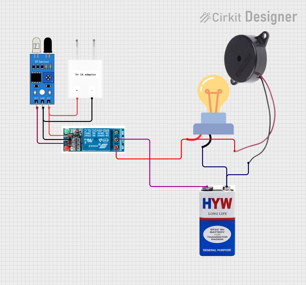
Circuit Documentation
Summary
The circuit in question appears to be designed to control an AC LED bulb and a buzzer using an IR sensor and a 5V relay. The IR sensor detects the presence of an object or motion and triggers the relay, which in turn switches on the LED bulb and the buzzer. The circuit is powered by a 5V adapter and a 9V battery. The 5V adapter supplies power to the IR sensor and the relay, while the 9V battery is used to power the LED bulb and the buzzer through the relay.
Component List
IR Sensor
- Pins: out, gnd, vcc
- Description: An infrared sensor used for detecting objects or motion.
5V Relay
- Pins: Normally Open, Common terminal, Normally Closed, In, GND, VCC
- Description: An electromechanical switch used for controlling high power devices with a low power signal.
5V Adapter
- Pins: AC In 1, AC In 2, 5V, GND
- Description: A power supply that converts AC to a 5V DC output.
9V Battery
- Pins: +, -
- Description: A power source used to provide electrical energy to the circuit.
Buzzer
- Pins: POSITIVE, NEGATIVE
- Description: An electronic device that emits sound when electrically energized.
LED Bulb AC
- Pins: +, -
- Description: A light-emitting diode bulb designed for AC power.
Comments
- Pins: N/A
- Description: Placeholder for additional information or notes about the circuit.
Wiring Details
IR Sensor
- out connected to Relay (In)
- gnd connected to 5V Adapter (GND) and Relay (GND)
- vcc connected to 5V Adapter (5V) and Relay (VCC)
5V Relay
- Normally Open connected to LED Bulb AC (+) and Buzzer (POSITIVE)
- Common terminal connected to 9V Battery (+)
- Normally Closed not connected
- In connected to IR Sensor (out)
- GND connected to IR Sensor (gnd) and 5V Adapter (GND)
- VCC connected to IR Sensor (vcc) and 5V Adapter (5V)
5V Adapter
- AC In 1 and AC In 2 connected to the AC mains supply
- 5V connected to IR Sensor (vcc) and Relay (VCC)
- GND connected to IR Sensor (gnd) and Relay (GND)
9V Battery
- + connected to Relay (Common terminal)
- - connected to LED Bulb AC (-) and Buzzer (NEGATIVE)
Buzzer
- POSITIVE connected to Relay (Normally Open)
- NEGATIVE connected to 9V Battery (-)
LED Bulb AC
- + connected to Relay (Normally Open)
- - connected to 9V Battery (-)
Documented Code
No code has been provided for any microcontrollers in the circuit. If the circuit is intended to be controlled by a microcontroller, the code responsible for handling the IR sensor input and controlling the relay would be documented in this section. Since no code is available, this section remains empty.