
Arduino-Controlled Bluetooth Robotic Vehicle with Relay-Switched Water Pump
View and Edit Project In Cirkit Designer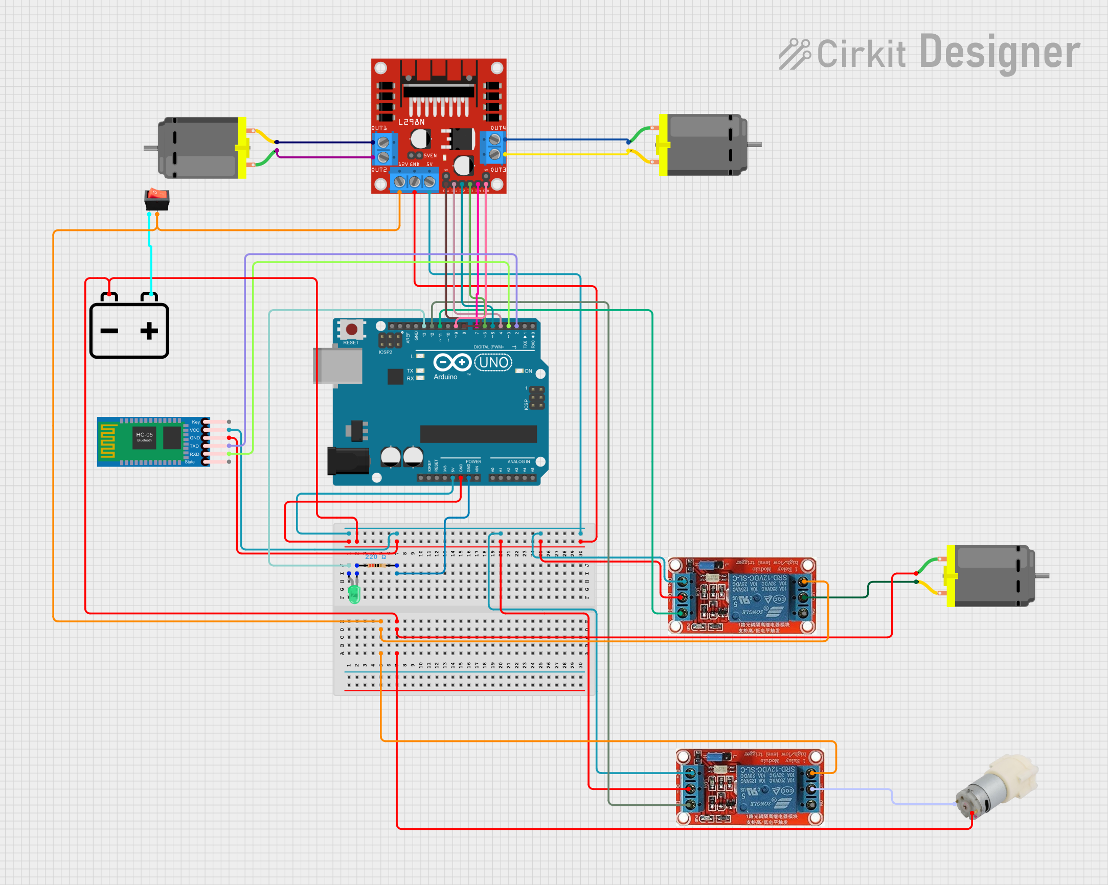
Circuit Documentation
Summary
This circuit is designed to control a set of DC motors and a water pump using an Arduino UNO microcontroller. The circuit includes a Bluetooth module for wireless communication, a motor driver to handle motor control signals from the Arduino, relays for switching high-power devices, and a rocker switch as a manual control interface. The circuit is powered by a 12V battery, and it includes a green LED indicator with a current-limiting resistor.
Component List
HC-05 Bluetooth Module
- A Bluetooth module for wireless communication with the microcontroller.
DC Motors
- Three DC motors are included in the circuit for various mechanical movements.
Water Pump 12V
- A 12V water pump used for pumping water.
Resistor (220 Ohms)
- A resistor with a resistance of 220 Ohms, likely used for current limiting for the LED.
LED: Two Pin (green)
- A green LED used as an indicator light.
Rocker Switch
- A manual switch to control the power flow in the circuit.
Arduino UNO
- A microcontroller board based on the ATmega328P, used for controlling the various components in the circuit.
L298N DC Motor Driver
- A motor driver module used to control the speed and direction of the DC motors.
12V Battery
- A power source for the circuit.
12V Relays
- Two relays used for switching higher power circuits with the microcontroller.
Wiring Details
HC-05 Bluetooth Module
- VCC connected to Arduino UNO 5V
- GND connected to common ground
- TXD connected to Arduino UNO D2
- RXD connected to Arduino UNO D3
DC Motors
- Motor 1 connected to L298N DC motor driver OUT1 and OUT2
- Motor 2 connected to L298N DC motor driver OUT3 and OUT4
- Motor 3 connected to 12V Relay COM (one of the relays)
Water Pump 12V
- Positive terminal connected to 12V Relay COM (the other relay)
- Negative terminal connected to common ground
Resistor (220 Ohms)
- One side connected to Arduino UNO GND
- The other side connected to the cathode of the green LED
LED: Two Pin (green)
- Anode connected to Arduino UNO D13
- Cathode connected to 220 Ohms resistor
Rocker Switch
- Input connected to 12V Battery positive terminal
- Output connected to L298N DC motor driver 12V and both 12V Relays NC
Arduino UNO
- GND connected to common ground
- 5V connected to HC-05 Bluetooth Module VCC and both 12V Relays DC+
- D13 connected to the anode of the green LED
- D12 and D11 connected to the IN pins of the 12V Relays
- D9 and D8 connected to L298N DC motor driver ENB and ENA
- D7 and D6 connected to L298N DC motor driver IN4 and IN3
- D5 and D4 connected to L298N DC motor driver IN2 and IN1
- D3 and D2 connected to HC-05 Bluetooth Module RXD and TXD
L298N DC Motor Driver
- 12V connected to Rocker Switch output
- GND connected to common ground
- 5V connected to Arduino UNO 5V
- Motor outputs connected to DC Motors as described above
- Control inputs connected to corresponding Arduino UNO pins
12V Battery
- Positive terminal connected to Rocker Switch input
- Negative terminal connected to common ground
12V Relays
- DC+ connected to Arduino UNO 5V
- DC- connected to common ground
- IN connected to Arduino UNO D12 and D11
- COM connected to DC Motor 3 and Water Pump 12V
- NC connected to L298N DC motor driver 12V
Documented Code
Arduino UNO Code (sketch.ino)
void setup() {
  // put your setup code here, to run once:

}

void loop() {
  // put your main code here, to run repeatedly:

}
Note: The provided code is a template and does not contain any functional code. It needs to be populated with the logic to control the motors, read Bluetooth commands, and manage the relay states.