Arduino Mega and NodeMCU Controlled Multi-Motor Driver System
Circuit Documentation
Summary
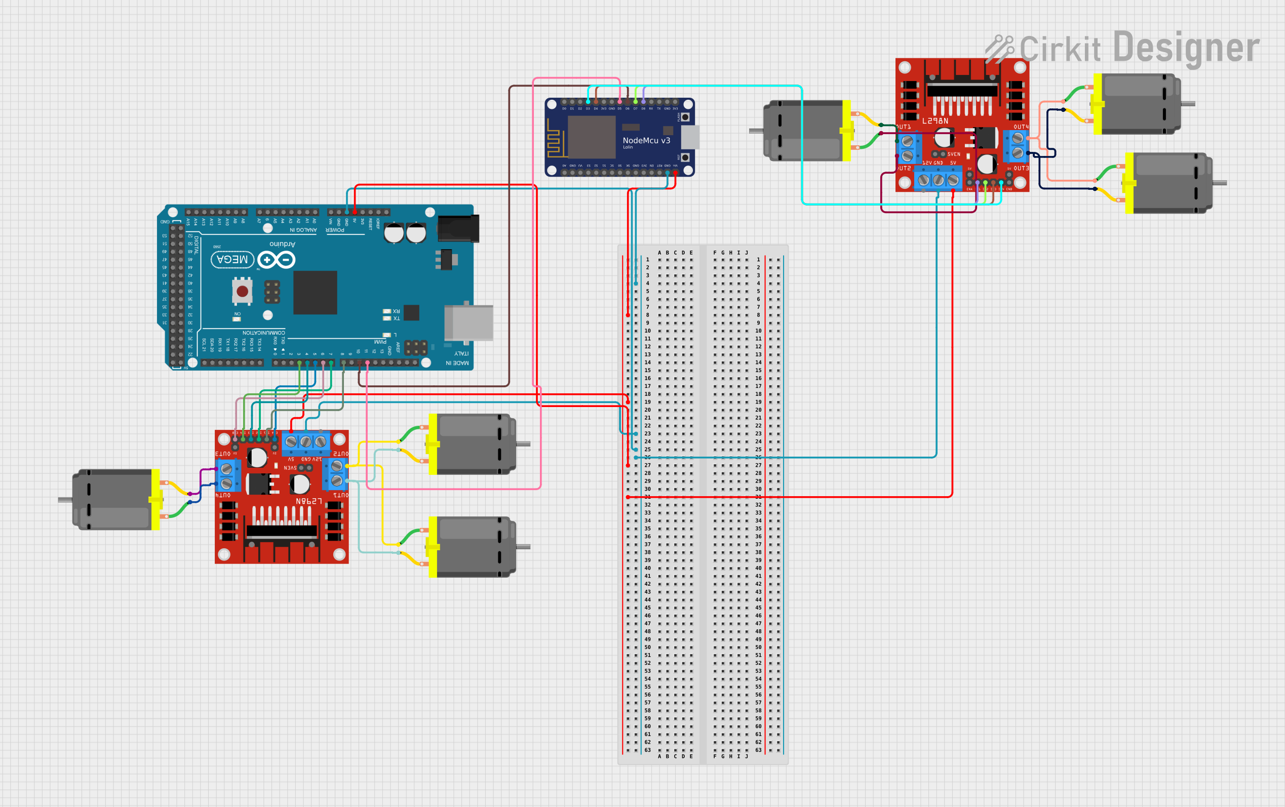
This circuit integrates an Arduino Mega 2560 with a NodeMCU V3 ESP8266 to control multiple DC motors via two L298N DC motor drivers. The Arduino Mega 2560 serves as the primary microcontroller, interfacing with the motor drivers to manage the direction and speed of the motors. The NodeMCU V3 ESP8266 is used for additional control and communication capabilities. The circuit is designed to provide a platform for motor control applications, such as robotics or automated systems.
Component List
Arduino Mega 2560
- Microcontroller board based on the ATmega2560
- Provides a large number of I/O pins, including PWM outputs and communication interfaces
NodeMCU V3 ESP8266
- Microcontroller board with Wi-Fi capability
- Based on the ESP8266 SoC, it offers GPIO, analog input, and serial communication
L298N DC Motor Driver (x2)
- Dual H-bridge motor driver module
- Capable of driving two DC motors or one stepper motor
DC Motor (x5)
- Standard DC motors for motion applications
- Connected to the motor driver for directional and speed control
Wiring Details
Arduino Mega 2560
GNDconnected to common ground5Vconnected to the 5V power railD3 PWMtoIN4on L298N (Motor Driver 1)D4 PWMtoIN3on L298N (Motor Driver 1)D5 PWMtoENAon L298N (Motor Driver 1)D6 PWMtoENBon L298N (Motor Driver 1)D7 PWMtoIN2on L298N (Motor Driver 1)D8 PWMtoIN1on L298N (Motor Driver 1)D10 PWMconnected toD6on NodeMCU V3 ESP8266D11 PWMconnected toD5on NodeMCU V3 ESP8266
NodeMCU V3 ESP8266
GNDconnected to common groundVinconnected to the 5V power railD3toIN4on L298N (Motor Driver 2)D4toIN3on L298N (Motor Driver 2)D7toIN2on L298N (Motor Driver 2)D8toIN1on L298N (Motor Driver 2)
L298N DC Motor Driver 1
GNDconnected to common ground5Vconnected to the 5V power railOUT1andOUT2connected to two DC Motors (Motor 1 and Motor 2)OUT3andOUT4connected to one DC Motor (Motor 3)
L298N DC Motor Driver 2
GNDconnected to common ground5Vconnected to the 5V power railOUT1andOUT2connected to one DC Motor (Motor 4)OUT3andOUT4connected to two DC Motors (Motor 5 and Motor 6)
DC Motors
- Each motor has two pins:
pin 1andpin 2 - Motors are connected to the respective outputs of the L298N motor drivers
Documented Code
Arduino Mega 2560 Code
#include <SoftwareSerial.h>

// Define the pins for SoftwareSerial
const int rxPin = D6; // RX pin for SoftwareSerial
const int txPin = D5; // TX pin for SoftwareSerial

SoftwareSerial mySerial(rxPin, txPin); // RX, TX

void setup() {
  Serial.begin(9600); // For debugging
  mySerial.begin(9600); // Baud rate for communication with Arduino Mega

  Serial.println("NodeMCU is ready");
}

void loop() {
  // Send a test command to Arduino Mega
  mySerial.println("TEST_COMMAND");

  // Check if there is any data from Arduino Mega
  if (mySerial.available()) {
    String receivedData = mySerial.readString();
    Serial.print("Received from Arduino Mega: ");
    Serial.println(receivedData);
  }

  delay(5000); // Wait for 5 seconds
}
This code snippet is for the Arduino Mega 2560, which sets up a SoftwareSerial communication link with the NodeMCU V3 ESP8266. It sends a test command to the NodeMCU and prints any received data to the serial monitor for debugging purposes. The communication operates at a baud rate of 9600.