
ESP32 and Logic Level Converter-Based Wi-Fi Controlled Interface
View and Edit Project In Cirkit Designer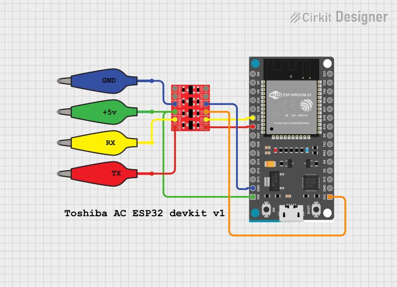
Circuit Documentation
Summary
This document provides a detailed overview of a circuit involving an ESP32 Devkit V1 microcontroller, a Bi-Directional Logic Level Converter, and several alligator clip cables. The circuit is designed to interface the ESP32 with other components that operate at different voltage levels. The document includes a component list, wiring details, and the embedded code used in the microcontrollers.
Component List
ESP32 Devkit V1
- Description: A development board featuring the ESP32 microcontroller, which includes Wi-Fi and Bluetooth capabilities.
- Pins: 3V3, GND, D15, D2, D4, RX2, TX2, D5, D18, D19, D21, RX0, TX0, D22, D23, EN, VP, VN, D34, D35, D32, D33, D25, D26, D27, D14, D12, D13, VIN
Bi-Directional Logic Level Converter
- Description: A module used to safely step down 5V signals to 3.3V and step up 3.3V to 5V.
- Pins: HV1, HV2, HV, GND, HV3, HV4, LV1, LV2, LV, LV3, LV4
12978-alligator_clip_cable_half-yellow
- Description: An alligator clip cable used for making temporary electrical connections.
- Pins: Pin, Alligator
12978-alligator_clip_cable_half-green
- Description: An alligator clip cable used for making temporary electrical connections.
- Pins: Pin, Alligator
12978-alligator_clip_cable_half-blue
- Description: An alligator clip cable used for making temporary electrical connections.
- Pins: Pin, Alligator
12978-alligator_clip_cable_half-red
- Description: An alligator clip cable used for making temporary electrical connections.
- Pins: Pin, Alligator
Comment
- Description: Placeholder for comments in the circuit design.
- Pins: None
Wiring Details
ESP32 Devkit V1
- 3V3 is connected to LV of the Bi-Directional Logic Level Converter.
- GND is connected to GND of the Bi-Directional Logic Level Converter.
- D32 is connected to LV2 of the Bi-Directional Logic Level Converter.
- D33 is connected to LV1 of the Bi-Directional Logic Level Converter.
- VIN is connected to HV of the Bi-Directional Logic Level Converter through the Pin of the green alligator clip cable.
Bi-Directional Logic Level Converter
- LV is connected to 3V3 of the ESP32 Devkit V1.
- GND is connected to GND of the ESP32 Devkit V1 and the Pin of the blue alligator clip cable.
- LV2 is connected to D32 of the ESP32 Devkit V1.
- LV1 is connected to D33 of the ESP32 Devkit V1.
- HV is connected to VIN of the ESP32 Devkit V1 through the Pin of the green alligator clip cable.
- HV1 is connected to the Pin of the red alligator clip cable.
- HV2 is connected to the Pin of the yellow alligator clip cable.
12978-alligator_clip_cable_half-yellow
- Pin is connected to HV2 of the Bi-Directional Logic Level Converter.
12978-alligator_clip_cable_half-green
- Pin is connected to HV of the Bi-Directional Logic Level Converter and VIN of the ESP32 Devkit V1.
12978-alligator_clip_cable_half-blue
- Pin is connected to GND of the Bi-Directional Logic Level Converter.
12978-alligator_clip_cable_half-red
- Pin is connected to HV1 of the Bi-Directional Logic Level Converter.
Documented Code
ESP32 Devkit V1 Code
void setup() {
  // put your setup code here, to run once:

}

void loop() {
  // put your main code here, to run repeatedly:

}
Bi-Directional Logic Level Converter Code
void setup() {
  // put your setup code here, to run once:

}

void loop() {
  // put your main code here, to run repeatedly:

}
This document provides a comprehensive overview of the circuit, including the components used, their connections, and the embedded code.