Cirkit Designer
Your all-in-one circuit design IDE
Home /
Project Documentation
Arduino Nano-Based Water Quality Monitoring System with OLED Display

Circuit Documentation
Summary
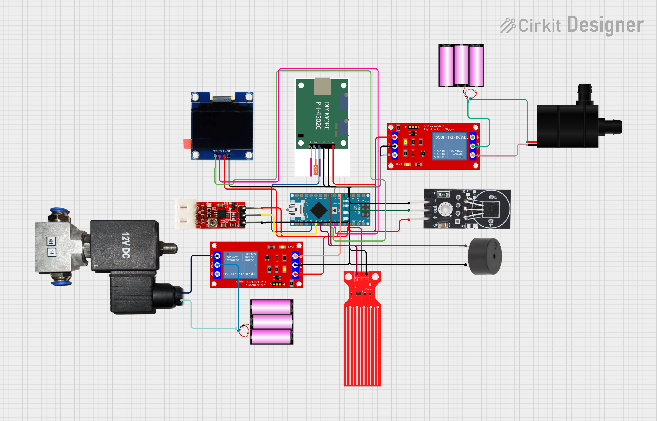
The circuit in question is designed to monitor and control a water system, featuring sensors for pH, turbidity, temperature, and water level. It includes an Arduino Nano as the central microcontroller, interfaced with various sensors and output devices such as a relay module, a buzzer, an OLED display, a water pump, and a pneumatic solenoid valve. The system reads sensor data, displays values on the OLED, and activates the pump and valve based on predefined threshold values.
Component List
Arduino Nano
- Microcontroller board based on the ATmega328P
- Offers a variety of digital and analog I/O pins
- Used as the central processing unit of the circuit
pH Sensor (ph4502c)
- Measures the pH level of the water
- Outputs an analog signal proportional to the pH level
Turbidity Module
- Measures the turbidity of the water
- Provides an analog output corresponding to the water's turbidity
DS18B20 Temperature Sensor
- Digital temperature sensor
- Measures the temperature of the water
Water Level Sensor
- Detects the water level in a tank or reservoir
- Outputs an analog signal based on the water level
Water Pump
- Electric pump for moving water
- Controlled by the Arduino via a relay
OLED 1.3" Display
- Small screen for displaying sensor readings and status information
- Communicates with the Arduino via I2C protocol
12V Pneumatic Solenoid Valve
- Electrically controlled valve for controlling air or water flow
- Actuated by the Arduino through a relay
12V Battery
- Provides power to the water pump and solenoid valve
1 Channel 5V Relay Module (x2)
- Electrically operated switch that allows the Arduino to control high power devices
- One relay controls the water pump, and the other controls the solenoid valve
Buzzer
- Emits an audible alert under certain conditions
- Controlled directly by the Arduino
Wiring Details
Arduino Nano
GNDconnected to the common ground netD2connected to DS18B20 Temperature Sensor OUTD3connected to Relay Module (Solenoid Valve) IND4connected to Relay Module (Pump) IND5connected to Buzzer PIN5Vconnected to the common 5V netA5connected to OLED SCLA4connected to OLED SDAA2connected to Water Level Sensor SIGA1connected to Turbidity Module OUTA0connected to pH Sensor Po
pH Sensor (ph4502c)
VCCconnected to the common 5V netG1andG2connected to the common ground netPoconnected to Arduino Nano A0
Turbidity Module
VCCconnected to the common 5V netGNDconnected to the common ground netOUTconnected to Arduino Nano A1
DS18B20 Temperature Sensor
VCCconnected to the common 5V netGNDconnected to the common ground netOUTconnected to Arduino Nano D2
Water Level Sensor
VCCconnected to the common 5V netGNDconnected to the common ground netSIGconnected to Arduino Nano A2
Water Pump
VCCconnected to 12V Battery (+)GNDconnected to Relay Module (Pump) N.O.
OLED 1.3" Display
VCCconnected to the common 5V netGNDconnected to the common ground netSCLconnected to Arduino Nano A5SDAconnected to Arduino Nano A4
12V Pneumatic Solenoid Valve
VCCconnected to Relay Module (Solenoid Valve) N.O.GNDconnected to 12V Battery (-)
12V Battery
+connected to Water Pump VCC and Relay Module (Solenoid Valve) COM-connected to Pneumatic Solenoid Valve GND and Relay Module (Pump) COM
1 Channel 5V Relay Module (for Solenoid Valve)
VCC+connected to the common 5V netVCC- (GND)connected to the common ground netINconnected to Arduino Nano D3N.O.connected to Pneumatic Solenoid Valve VCCCOMconnected to 12V Battery (+)
1 Channel 5V Relay Module (for Pump)
VCC+connected to the common 5V netVCC- (GND)connected to the common ground netINconnected to Arduino Nano D4N.O.connected to Water Pump GNDCOMconnected to 12V Battery (-)
Buzzer
PINconnected to Arduino Nano D5GNDconnected to the common ground net
Documented Code
#include <Wire.h>                        // For OLED Display
#include <Adafruit_GFX.h>                 // For OLED Display
#include <Adafruit_SSD1306.h>             // For OLED Display
#include <OneWire.h>                      // For DS18B20 Temperature Sensor
#include <DallasTemperature.h>            // For DS18B20 Temperature Sensor

#define SCREEN_WIDTH 128                  // OLED display width
#define SCREEN_HEIGHT 64                  // OLED display height
#define OLED_RESET -1                     // Reset pin (not used)
Adafruit_SSD1306 display(SCREEN_WIDTH, SCREEN_HEIGHT, &Wire, OLED_RESET);

// Pin Definitions
#define PH_SENSOR_PIN A0                  // pH Sensor connected to A0
#define TURBIDITY_SENSOR_PIN A1           // Turbidity Sensor connected to A1
#define WATER_LEVEL_SENSOR_PIN A2         // Water Level Sensor connected to A2
#define TEMP_SENSOR_PIN 2                 // DS18B20 Temperature Sensor on digital pin 2
#define RELAY_SOLENOID_PIN 3              // Relay for Solenoid Valve on digital pin 3
#define RELAY_PUMP_PIN 4                  // Relay for Pump on digital pin 4
#define BUZZER_PIN 5                      // Buzzer connected to digital pin 5

// DS18B20 Sensor Setup
OneWire oneWire(TEMP_SENSOR_PIN);
DallasTemperature sensors(&oneWire);

// Threshold values (You can adjust these based on your requirements)
float pHThresholdLow = 6.5;               // Lower pH threshold
float pHThresholdHigh = 8.0;              // Upper pH threshold
int turbidityThreshold = 300;             // Turbidity threshold (analog value)
int waterLevelThreshold = 500;            // Water level threshold (analog value)

// Variables
float pHValue;
int turbidityValue;
int waterLevelValue;
float temperatureValue;

void setup() {
  // Initialize serial communication for debugging
  Serial.begin(9600);

  // Initialize the OLED display
  if (!display.begin(SSD1306_SWITCHCAPVCC, 0x3C)) {  // Initialize OLED with I2C address 0x3C
    Serial.println(F("SSD1306 allocation failed"));
    for (;;);  // Loop forever if the display initialization fails
  }

  // Clear the display
  display.clearDisplay();
  display.display();

  // Initialize the DS18B20 temperature sensor
  sensors.begin();

  // Set pin modes for the relay, buzzer, etc.
  pinMode(RELAY_SOLENOID_PIN, OUTPUT);
  pinMode(RELAY_PUMP_PIN, OUTPUT);
  pinMode(BUZZER_PIN, OUTPUT);

  // Turn off relays and buzzer at startup
  digitalWrite(RELAY_SOLENOID_PIN, LOW);
  digitalWrite(RELAY_PUMP_PIN, LOW);
  digitalWrite(BUZZER_PIN, LOW);
}

void loop() {
  // Read sensor values
  pHValue = analogRead(PH_SENSOR_PIN);
  turbidityValue = analogRead(TURBIDITY_SENSOR_PIN);
  waterLevelValue = analogRead(WATER_LEVEL_SENSOR_PIN);

  // Get temperature readings
  sensors.requestTemperatures();
  temperatureValue = sensors.getTempCByIndex(0);

  // Display readings on the OLED
  display.clearDisplay();
  display.setTextSize(1);
  display.setTextColor(SSD1306_WHITE);
  display.setCursor(0, 0);

  display.print("pH: ");
  display.println(pHValue);

  display.print("Turbidity: ");
  display.println(turbidityValue);

  display.print("Water Level: ");
  display.println(waterLevelValue);

  display.print("Temperature: ");
  display.println(temperatureValue);

  display.display();

  // Control relays and buzzer based on thresholds
  if (pHValue < pHThresholdLow || pHValue > pHThresholdHigh || turbidityValue > turbidityThreshold) {
    digitalWrite(RELAY_SOLENOID_PIN, HIGH);  // Open solenoid valve
    digitalWrite(BUZZER_PIN, HIGH);          // Turn on buz