Cirkit Designer
Your all-in-one circuit design IDE
Home /
Project Documentation
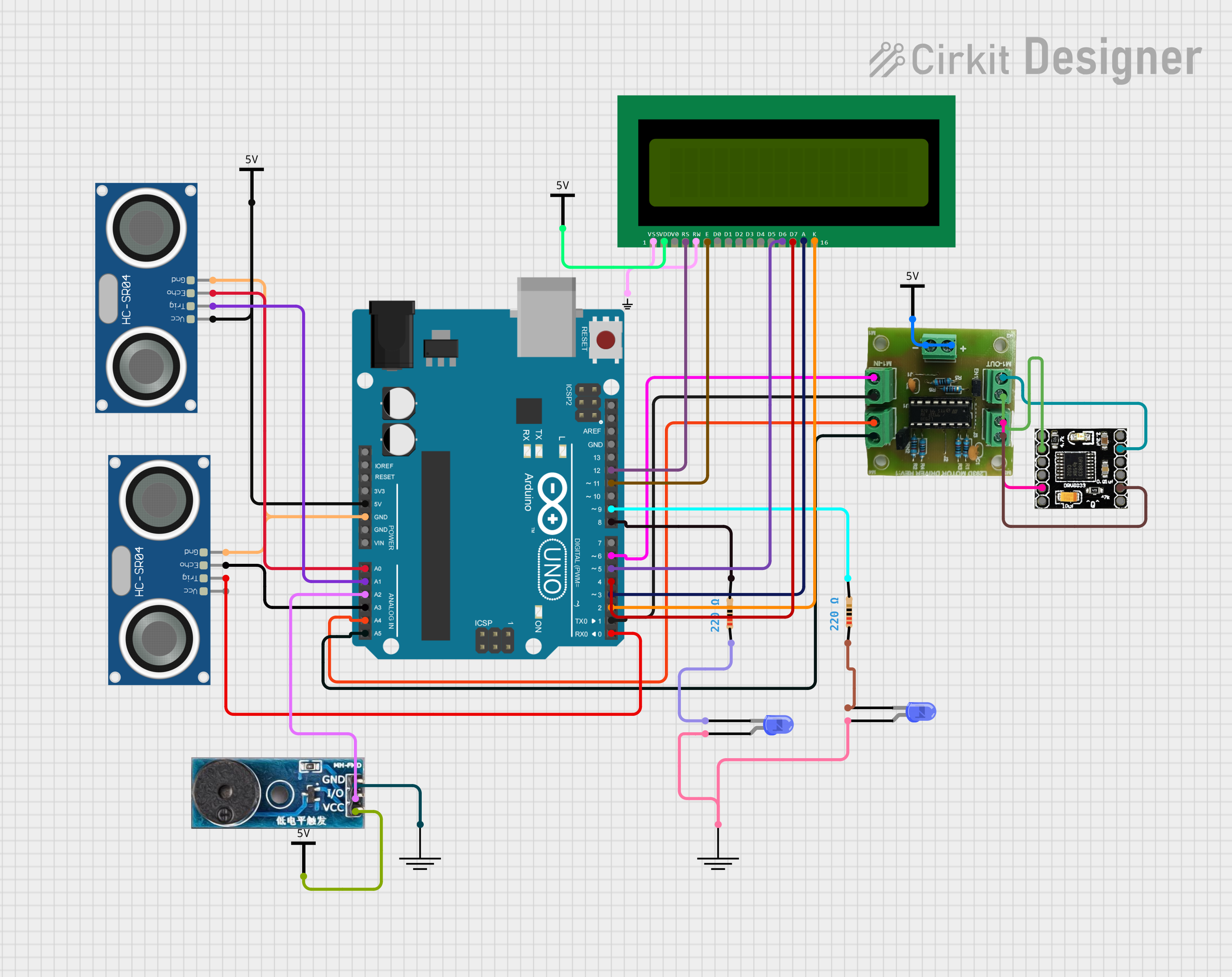
Arduino UNO-Based Ultrasonic Distance Measurement with LCD Display and Motor Control
Circuit Documentation
Summary of the Circuit
This circuit integrates various components controlled by an Arduino UNO microcontroller to perform a range of functions. The circuit includes ultrasonic sensors for distance measurement, a buzzer module for audio signaling, a 16x2 LCD for display, LEDs for visual indication, resistors for current limiting, and motor driver ICs for controlling motors. The Arduino UNO is programmed to manage these components, allowing for a complex interaction of sensory input, processing, and actuation/output.
Component List
Arduino UNO
- Microcontroller board based on the ATmega328P
- It has 14 digital input/output pins, 6 analog inputs, a 16 MHz quartz crystal, a USB connection, a power jack, an ICSP header, and a reset button.
HC-SR04 Ultrasonic Sensor (x2)
- Ultrasonic distance measuring module
- It has 4 pins: VCC, TRIG, ECHO, and GND.
Buzzer Module
- An audio signaling device
- It has 3 pins: GND, Vcc, and I/O.
16X2 LCD
- A liquid crystal display capable of displaying 16 characters per line across 2 lines
- It has 16 pins including data lines, power, contrast adjustment, and backlight.
Resistor (x2)
- Passive electrical component with a fixed value of resistance, 220 Ohms in this case
- It has 2 pins: pin1 and pin2.
LED: Two Pin (blue) (x2)
- A blue light-emitting diode for visual indication
- It has 2 pins: cathode and anode.
L293D
- A motor driver IC capable of driving two DC motors
- It has 10 pins for motor supply, motor outputs, and motor inputs.
Drv8833
- A motor driver IC
- It has 12 pins including motor outputs, inputs, power supply, and ground.
GND (x3)
- Ground reference points for the circuit
- Each has a single GND pin.
Vcc (x4)
- Power supply reference points for the circuit
- Each has a single Vcc pin.
Wiring Details
Arduino UNO
- 5V to Vcc of HC-SR04 Ultrasonic Sensor and Vcc power reference
- GND to GND of HC-SR04 Ultrasonic Sensor and Buzzer Module
- A0 to ECHO of HC-SR04 Ultrasonic Sensor
- A1 to TRIG of HC-SR04 Ultrasonic Sensor
- A2 to I/O of Buzzer Module
- A3 to ECHO of second HC-SR04 Ultrasonic Sensor
- A4 to M2-IN-A of L293D
- A5 to M2-IN-B of L293D
- D12 to RS of 16X2 LCD
- D11 to E of 16X2 LCD
- D9 to pin2 of a Resistor
- D8 to pin2 of another Resistor
- D6 to M1-IN-A of L293D
- D5 to D6 of 16X2 LCD
- D4 to D7 of 16X2 LCD
- D3 to A of 16X2 LCD
- D2 to K of 16X2 LCD
- D1 to M1-IN-B of L293D
- D0 to TRIG of second HC-SR04 Ultrasonic Sensor
HC-SR04 Ultrasonic Sensor
- VCC to 5V of Arduino UNO
- GND to GND of Arduino UNO
- ECHO to A0 of Arduino UNO
- TRIG to A1 of Arduino UNO
Buzzer Module
- I/O to A2 of Arduino UNO
- GND to GND power reference
- Vcc to Vcc power reference
16X2 LCD
- VSS and RW to Small GND
- VDD to Vcc power reference
- RS to D12 of Arduino UNO
- E to D11 of Arduino UNO
- D6 to D5 of Arduino UNO
- D7 to D4 of Arduino UNO
- A to D3 of Arduino UNO
- K to D2 of Arduino UNO
Resistor
- pin1 to cathode of LED
- pin2 to D9 of Arduino UNO
LED: Two Pin (blue)
- cathode to pin1 of Resistor
- anode to GND power reference
L293D
- Battery + to Vcc power reference
- Battery - to GND power reference
- M1-OUT-A to IN3 of Drv8833
- M1-OUT-B to OUT1 of Drv8833
- M2-OUT-B to IN1 of Drv8833
- M2-OUT-A to OUT4 of Drv8833
- M1-IN-A to D6 of Arduino UNO
- M1-IN-B to D1 of Arduino UNO
- M2-IN-A to A4 of Arduino UNO
- M2-IN-B to A5 of Arduino UNO
Drv8833
- IN3 to M1-OUT-A of L293D
- OUT1 to M1-OUT-B of L293D
- IN1 to M2-OUT-B of L293D
- OUT4 to M2-OUT-A of L293D
Documented Code
// Code for Arduino UNO
const int trigPin2 = 0; // D0
const int ledPin1 = 8;  // D8
const int ledPin2 = 9;  // D9
const int motorPin1 = 6; // D6
const int motorPin2 = 1; // D1
const int lcdRs = 12;   // D12
const int lcdEn = 11;   // D11
const int lcdD4 = 5;    // D5
const int lcdD5 = 6;    // D6
const int lcdD6 = 7;    // D7
const int lcdD7 = 4;    // D4

void setup() {
  // Initialize pins as outputs or inputs as needed
  pinMode(trigPin2, OUTPUT);
  pinMode(ledPin1, OUTPUT);
  pinMode(ledPin2, OUTPUT);
  pinMode(motorPin1, OUTPUT);
  pinMode(motorPin2, OUTPUT);
  pinMode(lcdRs, OUTPUT);
  pinMode(lcdEn, OUTPUT);
  pinMode(lcdD4, OUTPUT);
  pinMode(lcdD5, OUTPUT);
  pinMode(lcdD6, OUTPUT);
  pinMode(lcdD7, OUTPUT);
}

void loop() {
  // Your main code logic here
}
This code snippet is a basic setup for the Arduino UNO, initializing the pins connected to the various components in the circuit. The loop function is left empty, to be filled with the main logic of the application.