
Circuit Documentation
Summary of the Circuit
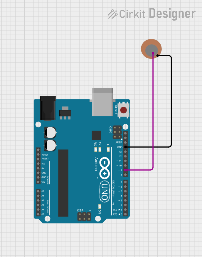
The circuit consists of an Arduino UNO microcontroller board and a Piezo Sensor. The Arduino UNO is used as the central processing unit of the circuit, capable of reading inputs from the Piezo Sensor and executing embedded code to perform specific tasks. The Piezo Sensor is connected to the Arduino UNO and is used to detect vibrations or pressure changes.
Component List
Arduino UNO
- Description: A microcontroller board based on the ATmega328P.
- Pins: UNUSED, IOREF, Reset, 3.3V, 5V, GND, Vin, A0 to A5, SCL, SDA, AREF, D0 to D13.
- Purpose: Acts as the central processing unit of the circuit, interfacing with sensors and other components.
Piezo Sensor
- Description: A sensor that generates an electrical charge in response to applied mechanical stress.
- Pins: + (positive), - (negative).
- Purpose: Detects vibrations or pressure changes and provides an electrical signal to the Arduino UNO.
Wiring Details
Arduino UNO
- GND: Connected to the negative (-) pin of the Piezo Sensor.
- D9: Connected to the positive (+) pin of the Piezo Sensor.
Piezo Sensor
- + (positive): Connected to pin D9 on the Arduino UNO.
- - (negative): Connected to the GND pin on the Arduino UNO.
Documented Code
Arduino UNO Code (sketch.ino)
void setup() {
  // put your setup code here, to run once:

}

void loop() {
  // put your main code here, to run repeatedly:

}
Additional Notes
The code provided for the Arduino UNO is a template with empty
setup()andloop()functions. Thesetup()function is intended to contain initialization code that runs once when the device is powered on or reset. Theloop()function is designed to contain the main logic of the program, which runs repeatedly as long as the device is powered.The additional file "documentation.txt" associated with the Arduino UNO does not contain any code or comments. It is likely intended for supplementary notes or instructions related to the embedded code or circuit operation.