Cirkit Designer
Your all-in-one circuit design IDE
Home /
Project Documentation
Arduino UNO Controlled LED Indicator with Pushbutton
Circuit Documentation
Summary
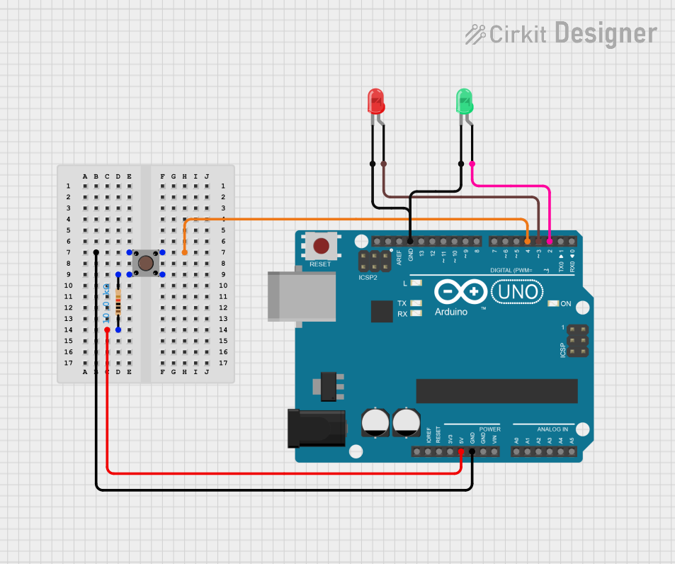
This circuit consists of an Arduino UNO microcontroller, a pushbutton, two LEDs (one red and one green), and a resistor. The pushbutton is used to control the LEDs, which are connected to the Arduino UNO. The resistor is used to limit the current flowing through the pushbutton.
Component List
Arduino UNO
- Description: A microcontroller board based on the ATmega328P.
- Pins: UNUSED, IOREF, Reset, 3.3V, 5V, GND, Vin, A0, A1, A2, A3, A4, A5, SCL, SDA, AREF, D13, D12, D11, D10, D9, D8, D7, D6, D5, D4, D3, D2, D1, D0
Pushbutton
- Description: A simple pushbutton switch.
- Pins: Pin 3 (out), Pin 4 (out), Pin 1 (in), Pin 2 (in)
LED: Two Pin (red)
- Description: A red LED with two pins.
- Pins: cathode, anode
LED: Two Pin (green)
- Description: A green LED with two pins.
- Pins: cathode, anode
Resistor
- Description: A resistor with a resistance of 10k Ohms.
- Pins: pin1, pin2
- Properties:
- Resistance: 10k Ohms
Wiring Details
Arduino UNO
- GND: Connected to Pin 3 (out) of the Pushbutton and cathode of both LEDs.
- D4: Connected to Pin 4 (out) of the Pushbutton.
- 5V: Connected to pin1 of the Resistor.
- D3: Connected to anode of the red LED.
- D2: Connected to anode of the green LED.
Pushbutton
- Pin 3 (out): Connected to GND of the Arduino UNO.
- Pin 4 (out): Connected to D4 of the Arduino UNO.
- Pin 1 (in): Connected to pin2 of the Resistor.
- Pin 2 (in): Not connected.
LED: Two Pin (red)
- cathode: Connected to GND of the Arduino UNO.
- anode: Connected to D3 of the Arduino UNO.
LED: Two Pin (green)
- cathode: Connected to GND of the Arduino UNO.
- anode: Connected to D2 of the Arduino UNO.
Resistor
- pin1: Connected to 5V of the Arduino UNO.
- pin2: Connected to Pin 1 (in) of the Pushbutton.
Code
Arduino UNO Code (sketch.ino)
void setup() {
  // put your setup code here, to run once:

}

void loop() {
  // put your main code here, to run repeatedly:

}
Documentation (documentation.txt)
This documentation provides a comprehensive overview of the circuit, including a summary, detailed component list, wiring details, and the code used in the Arduino UNO.