
Circuit Documentation
Summary of the Circuit
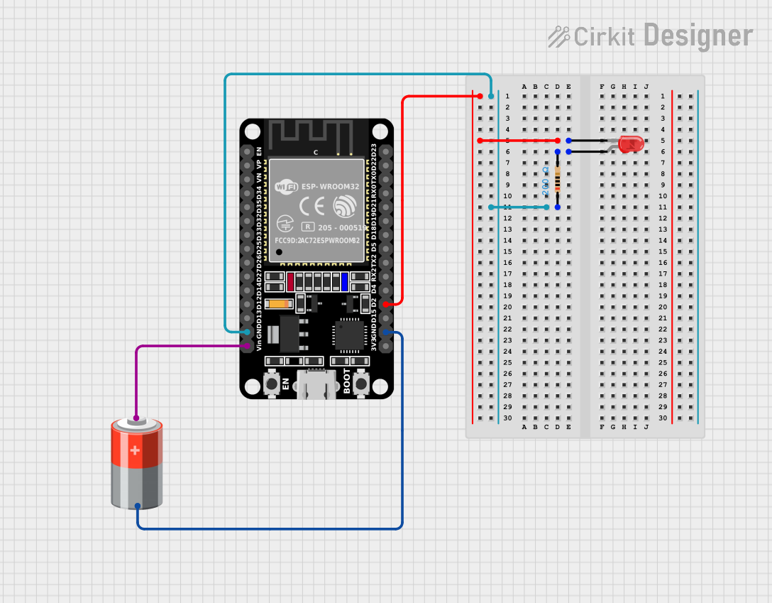
This circuit is designed around the ESP32 microcontroller, which is a versatile and powerful chip with Wi-Fi and Bluetooth capabilities. The circuit includes a simple LED indicator and a current-limiting resistor, powered by a 5V battery. The LED is controlled by the ESP32, which toggles the LED on and off with a 2-second interval, demonstrating basic digital output functionality.
Component List
ESP32 (30 pin)
- Description: A 30-pin microcontroller with Wi-Fi and Bluetooth capabilities.
- Pins: EN, VP, VN, D34, D35, D32, D33, D25, D26, D27, D14, D12, D13, GND, Vin, D23, D22, TX0, RX0, D21, D19, D18, D5, TX2, RX2, D4, D2, D15, 3V3
- Purpose: Acts as the central processing unit of the circuit, controlling the LED.
LED: Two Pin (red)
- Description: A basic red LED with two pins: anode and cathode.
- Pins: cathode, anode
- Purpose: Serves as a visual indicator, toggling on and off as controlled by the ESP32.
Resistor
- Description: A passive two-pin component that limits the current through the LED.
- Pins: pin1, pin2
- Properties: Resistance - 200 Ohms
- Purpose: Prevents excessive current from flowing through the LED, which could otherwise damage it.
5v Battery
- Description: A power source providing a constant 5V.
- Pins: + (positive), - (negative)
- Purpose: Supplies the necessary power to the circuit.
Wiring Details
ESP32 (30 pin)
- GND: Connected to the negative terminal of the battery and one pin of the resistor.
- Vin: Connected to the positive terminal of the battery.
- D2: Connected to the cathode of the LED.
LED: Two Pin (red)
- Cathode: Connected to pin D2 of the ESP32.
- Anode: Connected to one pin of the resistor.
Resistor
- Pin1: Connected to the GND pin of the ESP32.
- Pin2: Connected to the anode of the LED.
5v Battery
- + (Positive): Connected to the Vin pin of the ESP32.
- - (Negative): Connected to the GND pin of the ESP32.
Documented Code
// Code for controlling an LED using ESP32
int ledpin = 2; // LED connected to digital pin 2

void setup() {
    pinMode(ledpin, OUTPUT); // Initialize digital pin as an output
}

void loop() {
    digitalWrite(ledpin, HIGH); // Turn the LED on
    delay(2000);                // Wait for 2 seconds

    digitalWrite(ledpin, LOW);  // Turn the LED off
    delay(2000);                // Wait for 2 seconds
}
File Name: sketch.ino
Description: This code configures pin D2 of the ESP32 as an output to control the LED. In the loop function, it turns the LED on for 2 seconds and then off for 2 seconds, creating a blinking effect.