Cirkit Designer
Your all-in-one circuit design IDE
Home /
Project Documentation
Arduino-Based Vibration and Motion Detection System with LCD Display
Circuit Documentation
Summary
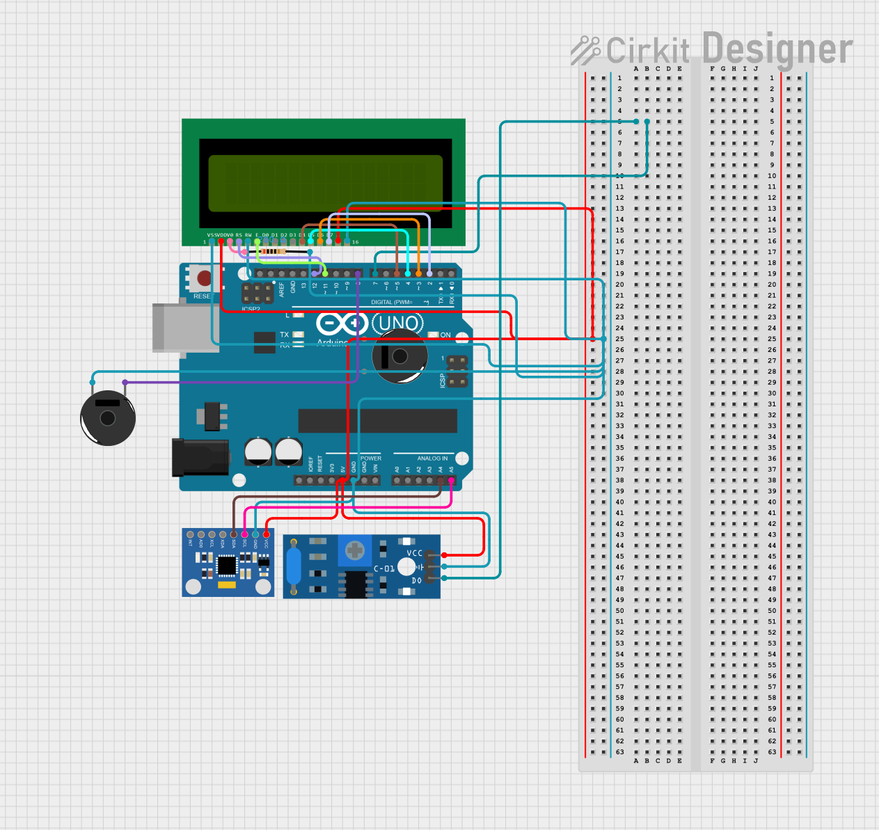
This circuit integrates an Arduino UNO microcontroller with various sensors and output devices, including a vibration sensor, an accelerometer/gyroscope, a piezo buzzer, and a 16x2 LCD display. The circuit is designed to detect vibrations and display relevant data on the LCD while providing auditory feedback through the buzzer.
Component List
SW-420 Vibration Sensor
- Description: Detects vibrations and provides a digital output.
- Pins: VCC, Ground, Digital output
MPU6050 Accelerometer + Gyroscope (Wokwi Compatible)
- Description: Measures acceleration and angular velocity.
- Pins: INT, AD0, XCL, XDA, SDA, SCL, GND, VCC
Arduino UNO
- Description: Microcontroller board based on the ATmega328P.
- Pins: UNUSED, IOREF, Reset, 3.3V, 5V, GND, Vin, A0, A1, A2, A3, A4, A5, SCL, SDA, AREF, D13, D12, D11, D10, D9, D8, D7, D6, D5, D4, D3, D2, D1, D0
Piezo Buzzer
- Description: Produces sound when a voltage is applied.
- Pins: Pin 1, Pin 2
16X2 LCD
- Description: Displays alphanumeric characters.
- Pins: VSS, VDD, V0, RS, RW, E, D1, D0, D2, D3, D4, D6, D5, D7, A, K
Resistor
- Description: Limits current flow.
- Properties: Resistance: 200 Ohms
- Pins: Pin 1, Pin 2
Wiring Details
SW-420 Vibration Sensor
- VCC connected to Arduino UNO 5V
- Ground connected to Arduino UNO GND
- Digital output connected to Arduino UNO D7
MPU6050 Accelerometer + Gyroscope (Wokwi Compatible)
- VCC connected to Arduino UNO 5V
- GND connected to Arduino UNO GND
- SDA connected to Arduino UNO A4
- SCL connected to Arduino UNO A5
Arduino UNO
- 5V connected to 16X2 LCD VDD, 16X2 LCD A, SW-420 Vibration Sensor VCC, MPU6050 VCC
- GND connected to Resistor Pin 2, Piezo Buzzer Pin 2, 16X2 LCD VSS, 16X2 LCD K, 16X2 LCD RW, SW-420 Vibration Sensor Ground, MPU6050 GND
- D7 connected to SW-420 Vibration Sensor Digital output
- A4 connected to MPU6050 SDA
- A5 connected to MPU6050 SCL
- D12 connected to 16X2 LCD RS
- D11 connected to 16X2 LCD E
- D8 connected to Piezo Buzzer Pin 1
- D5 connected to 16X2 LCD D4
- D4 connected to 16X2 LCD D5
- D3 connected to 16X2 LCD D6
- D2 connected to 16X2 LCD D7
Piezo Buzzer
- Pin 1 connected to Arduino UNO D8
- Pin 2 connected to Arduino UNO GND through Resistor Pin 2
16X2 LCD
- VDD connected to Arduino UNO 5V
- A connected to Arduino UNO 5V
- VSS connected to Arduino UNO GND
- K connected to Arduino UNO GND
- RW connected to Arduino UNO GND
- RS connected to Arduino UNO D12
- E connected to Arduino UNO D11
- D4 connected to Arduino UNO D5
- D5 connected to Arduino UNO D4
- D6 connected to Arduino UNO D3
- D7 connected to Arduino UNO D2
- V0 connected to Resistor Pin 1
Resistor
- Pin 1 connected to 16X2 LCD V0
- Pin 2 connected to Arduino UNO GND
Documented Code
Arduino UNO Code (sketch.ino)
void setup() {
  // put your setup code here, to run once:

}

void loop() {
  // put your main code here, to run repeatedly:

}
This code initializes the Arduino UNO and contains placeholders for setup and loop functions where the main logic of the circuit will be implemented.