
Arduino UNO-Based Smart Sensor System with GPS, GSM, and Bluetooth Connectivity
View and Edit Project In Cirkit Designer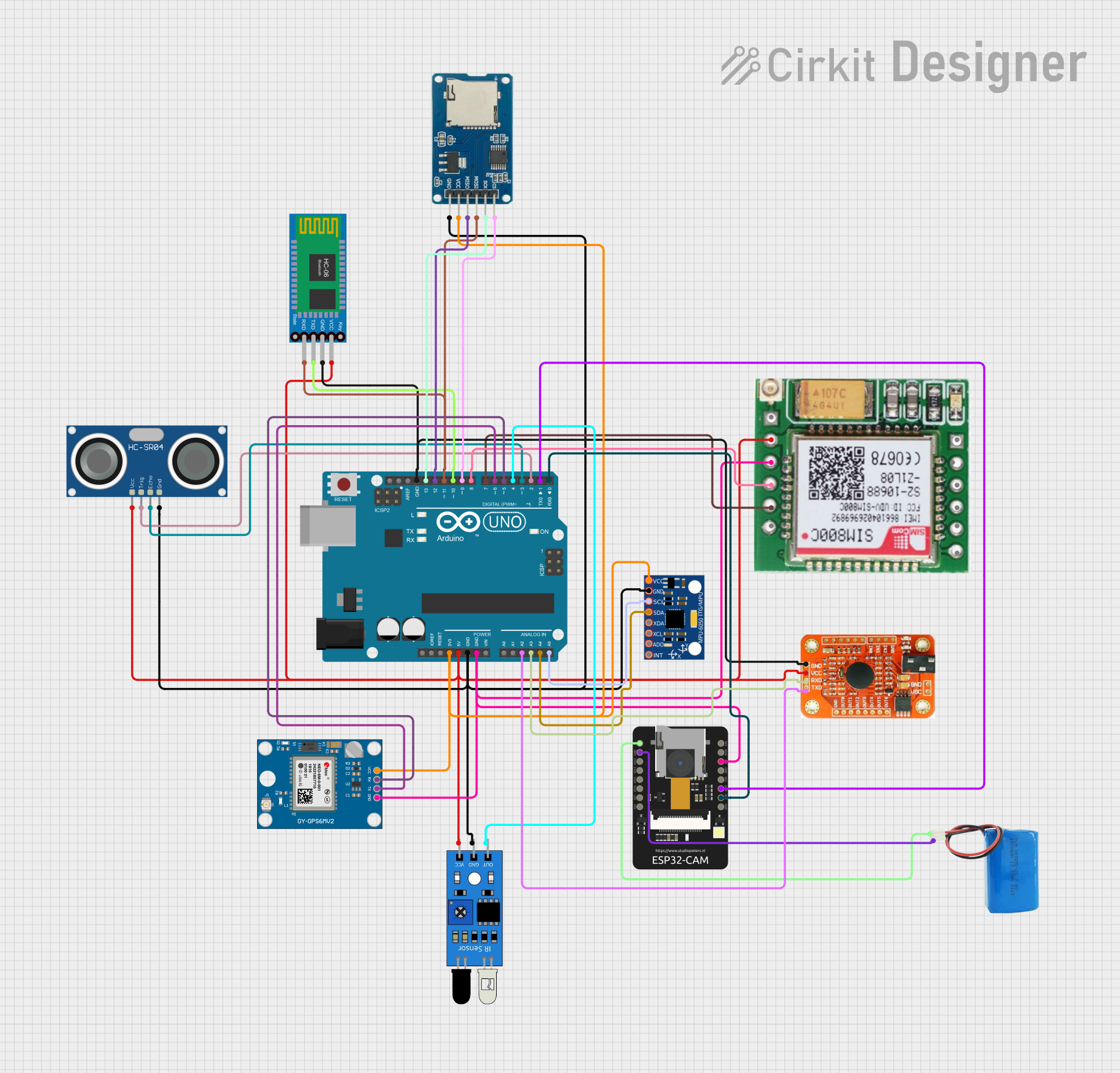
Circuit Documentation
Summary
This document provides a detailed overview of a circuit that integrates various sensors, communication modules, and a microcontroller to create a comprehensive system. The circuit includes an Arduino UNO as the central microcontroller, interfacing with multiple sensors and modules such as an MPU-6050 accelerometer, HC-SR04 ultrasonic sensor, Bluetooth HC-06, Neo 6M GPS module, ESP32-CAM, IR sensor, Micro SD card module, SIM800c GSM module, and a voice recognition module. The system is powered by a 5V battery.
Component List
MPU-6050
- Description: Accelerometer and Gyroscope sensor
- Pins: VCC, GND, SCL, SDA, XDA, XCL, AD0, INT
HC-SR04 Ultrasonic Sensor
- Description: Ultrasonic distance sensor
- Pins: VCC, TRIG, ECHO, GND
Bluetooth HC-06
- Description: Bluetooth communication module
- Pins: VCC, GND, TXD, RXD
Neo 6M GPS Module
- Description: GPS module for location tracking
- Pins: GND, TX, RX, VCC
ESP32-CAM
- Description: Camera module with Wi-Fi and Bluetooth
- Pins: 5V, GND, IO12, IO13, IO15, IO14, IO2, IO4, VOT, VOR, VCC, IO0, IO16, 3V3
Arduino UNO
- Description: Microcontroller board
- Pins: UNUSED, IOREF, Reset, 3.3V, 5V, GND, Vin, A0, A1, A2, A3, A4, A5, SCL, SDA, AREF, D13, D12, D11, D10, D9, D8, D7, D6, D5, D4, D3, D2, D1, D0
IR Sensor
- Description: Infrared sensor
- Pins: out, gnd, vcc
Micro SD Card Module
- Description: SD card module for data storage
- Pins: cs, sck, mosi, miso, vcc, gnd
SIM800c GSM Module
- Description: GSM module for communication
- Pins: SPK-, SPK+, MIC-, MIC+, DTR, RING, GND, TXD, RXD, LINK GND, ANT, VCC(3.7 - 4.2)
5V Battery
- Description: Power source
- Pins: positive, negative
Voice Recognition Module
- Description: Module for voice command recognition
- Pins: GND, VCC, RDX, RTX
Wiring Details
MPU-6050
- VCC: Connected to Arduino UNO 3.3V
- GND: Connected to Arduino UNO GND
- SCL: Connected to Arduino UNO A5
- SDA: Connected to Arduino UNO A4
HC-SR04 Ultrasonic Sensor
- VCC: Connected to Arduino UNO 5V
- GND: Connected to Arduino UNO GND
- TRIG: Connected to Arduino UNO D2
- ECHO: Connected to Arduino UNO D3
Bluetooth HC-06
- VCC: Connected to Arduino UNO 5V
- GND: Connected to Arduino UNO GND
- TXD: Connected to Arduino UNO D10
- RXD: Connected to Arduino UNO D11
Neo 6M GPS Module
- GND: Connected to Arduino UNO GND
- TX: Connected to Arduino UNO D6
- RX: Connected to Arduino UNO D5
- VCC: Connected to Arduino UNO 3.3V
ESP32-CAM
- 5V: Connected to 5V battery positive
- GND: Connected to 5V battery negative
- VOT: Connected to Arduino UNO D0
- VOR: Connected to Arduino UNO D1
- IO0: Connected to Arduino UNO GND
Arduino UNO
- 3.3V: Connected to MPU-6050 VCC, Neo 6M GPS Module VCC, Micro SD Card Module VCC
- 5V: Connected to HC-SR04 Ultrasonic Sensor VCC, Bluetooth HC-06 VCC, SIM800c GSM Module VCC, Voice Recognition Module VCC, IR Sensor VCC
- GND: Connected to MPU-6050 GND, HC-SR04 Ultrasonic Sensor GND, Bluetooth HC-06 GND, Neo 6M GPS Module GND, IR Sensor GND, Micro SD Card Module GND, SIM800c GSM Module LINK GND, Voice Recognition Module GND
- A2: Connected to Voice Recognition Module RTX
- A3: Connected to Voice Recognition Module RDX
- A4: Connected to MPU-6050 SDA
- A5: Connected to MPU-6050 SCL
- D2: Connected to HC-SR04 Ultrasonic Sensor TRIG
- D3: Connected to HC-SR04 Ultrasonic Sensor ECHO
- D4: Connected to IR Sensor out
- D5: Connected to Neo 6M GPS Module RX
- D6: Connected to Neo 6M GPS Module TX
- D7: Connected to SIM800c GSM Module TXD
- D8: Connected to SIM800c GSM Module RXD
- D9: Connected to Micro SD Card Module cs
- D10: Connected to Bluetooth HC-06 TXD
- D11: Connected to Bluetooth HC-06 RXD, Micro SD Card Module mosi
- D12: Connected to Micro SD Card Module miso
- D13: Connected to Micro SD Card Module sck
IR Sensor
- out: Connected to Arduino UNO D4
- gnd: Connected to Arduino UNO GND
- vcc: Connected to Arduino UNO 5V
Micro SD Card Module
- cs: Connected to Arduino UNO D9
- sck: Connected to Arduino UNO D13
- mosi: Connected to Arduino UNO D11
- miso: Connected to Arduino UNO D12
- vcc: Connected to Arduino UNO 3.3V
- gnd: Connected to Arduino UNO GND
SIM800c GSM Module
- VCC(3.7 - 4.2): Connected to Arduino UNO 5V
- GND: Connected to Arduino UNO GND
- TXD: Connected to Arduino UNO D7
- RXD: Connected to Arduino UNO D8
- LINK GND: Connected to Arduino UNO GND
5V Battery
- positive: Connected to ESP32-CAM 5V
- negative: Connected to ESP32-CAM GND
Voice Recognition Module
- GND: Connected to Arduino UNO GND
- VCC: Connected to Arduino UNO 5V
- RDX: Connected to Arduino UNO A3
- RTX: Connected to Arduino UNO A2
Documented Code
#include <Wire.h>
#include <MPU6050.h>
#include <SoftwareSerial.h>
#include <TinyGPS++.h>
#include <SPI.h>
#include <SD.h>

// Define pins for sensors
#define trigPin 2
#define echoPin 3
#define irSensorPin 4
#define gpsTxPin 6
#define gpsRxPin 5
#define gsmTxPin 7
#define gsmRxPin 8
#define sdPin 9  // for SD card module (SPI)

SoftwareSerial gsmSerial(gsmTxPin, gsmRxPin);
SoftwareSerial btSerial(10, 11);  // Update to unused pins
TinyGPSPlus gps;
MPU6050 mpu;

File logFile;

long duration;
int distance;
char gpsData[100];
String gpsLocation;

// Emergency contact number
const String emergencyNumber = "YOUR_EMERGENCY_NUMBER";

void setup() {
  Serial.begin(9600);
  gsmSerial.begin(9600);
  btSerial.begin(9600);
  Wire.begin();

  // Initialize sensors
  mpu.initialize();
  pinMode(trigPin, OUTPUT);
  pinMode(echoPin, INPUT);
  pinMode(irSensorPin, INPUT);

  // Initialize GSM
  gsmSerial.println("AT"); // Test GSM module
  delay(1000);
  gsmSerial.println("AT+CMGF=1"); // Set SMS mode
  delay(1000);

  // Initialize GPS
  Serial.println("GPS Initialized");

  // Initialize SD card
  if (!SD.begin(sdPin)) {
    Serial.println("SD card initialization failed.");
    return;
  }
  log