Cirkit Designer
Your all-in-one circuit design IDE
Home /
Project Documentation
Arduino UNO PIR Motion Sensor Interface
Circuit Documentation
Summary of the Circuit
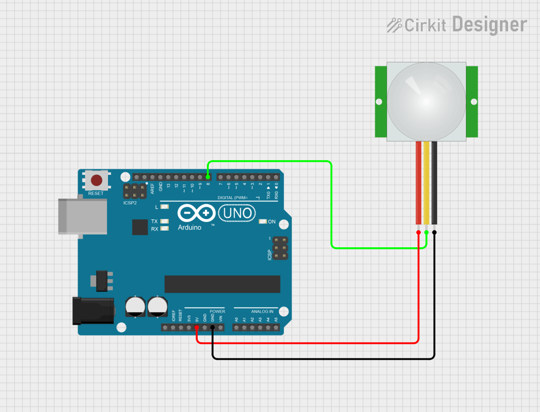
This circuit integrates a PIR (Passive Infrared) sensor with an Arduino UNO microcontroller. The purpose of the circuit is to detect motion through the PIR sensor and respond to the detection by turning on an LED connected to the Arduino UNO. Additionally, the Arduino UNO sends messages to the serial monitor indicating the detection of motion or its cessation.
Component List
PIR Sensor
- Description: A sensor that detects motion by measuring changes in the infrared levels emitted by surrounding objects.
- Pins:
VDD: Power supply input.SIG: Signal output, goes high when motion is detected.GND: Ground connection.
Arduino UNO
- Description: A microcontroller board based on the ATmega328P, widely used for building digital devices and interactive objects that can sense and control objects in the physical and digital world.
- Pins:
5V: Regulated power supply output.GND: Ground connection.D8: Digital I/O pin used to receive the signal from the PIR sensor.D13: Digital I/O pin used to control an LED.
Wiring Details
PIR Sensor
VDDconnected to Arduino UNO5V.SIGconnected to Arduino UNOD8.GNDconnected to Arduino UNOGND.
Arduino UNO
5Vprovides power to the PIR sensor.GNDis the common ground for the circuit.D8receives the signal from the PIR sensor.D13controls an LED indicating motion detection status.
Documented Code
/*
  PIR Sensor-Arduino UNO Interface Code
  This code interfaces a PIR sensor with an Arduino UNO. When motion is detected,
  an LED on pin D13 is turned on and a message is sent to the serial monitor. When
  motion is no longer detected, the LED is turned off and another message is sent.
*/

// Define the pin connections
int ledPin = 13;                // LED connected to pin D13
int inputPin = 8;               // PIR sensor signal on pin D8
int pirState = LOW;             // Start assuming no motion detected
int val = 0;                    // Variable for reading pin status

void setup() {
  pinMode(ledPin, OUTPUT);      // Declare LED as output
  pinMode(inputPin, INPUT);     // Declare PIR sensor signal as input

  Serial.begin(9600);           // Start serial at 9600 bps
}

void loop() {
  val = digitalRead(inputPin);  // Read PIR sensor signal

  if (val == HIGH) {            // If motion detected
    digitalWrite(ledPin, HIGH); // Turn LED ON

    if (pirState == LOW) {
      Serial.println("Motion detected!"); // Message for detection
      pirState = HIGH;                    // Update PIR state
    }
  } else {                      // If no motion
    digitalWrite(ledPin, LOW);  // Turn LED OFF

    if (pirState == HIGH) {
      Serial.println("Motion ended!"); // Message for motion end
      pirState = LOW;                  // Update PIR state
    }
  }
}
The code is written for the Arduino UNO and is responsible for reading the signal from the PIR sensor connected to pin D8. When motion is detected, the LED connected to pin D13 is turned on, and a message is printed to the serial monitor. When the motion stops, the LED is turned off, and another message is printed to the serial monitor.