
Arduino UNO with BMP280 Sensor and I2C LCD Display Interface
View and Edit Project In Cirkit Designer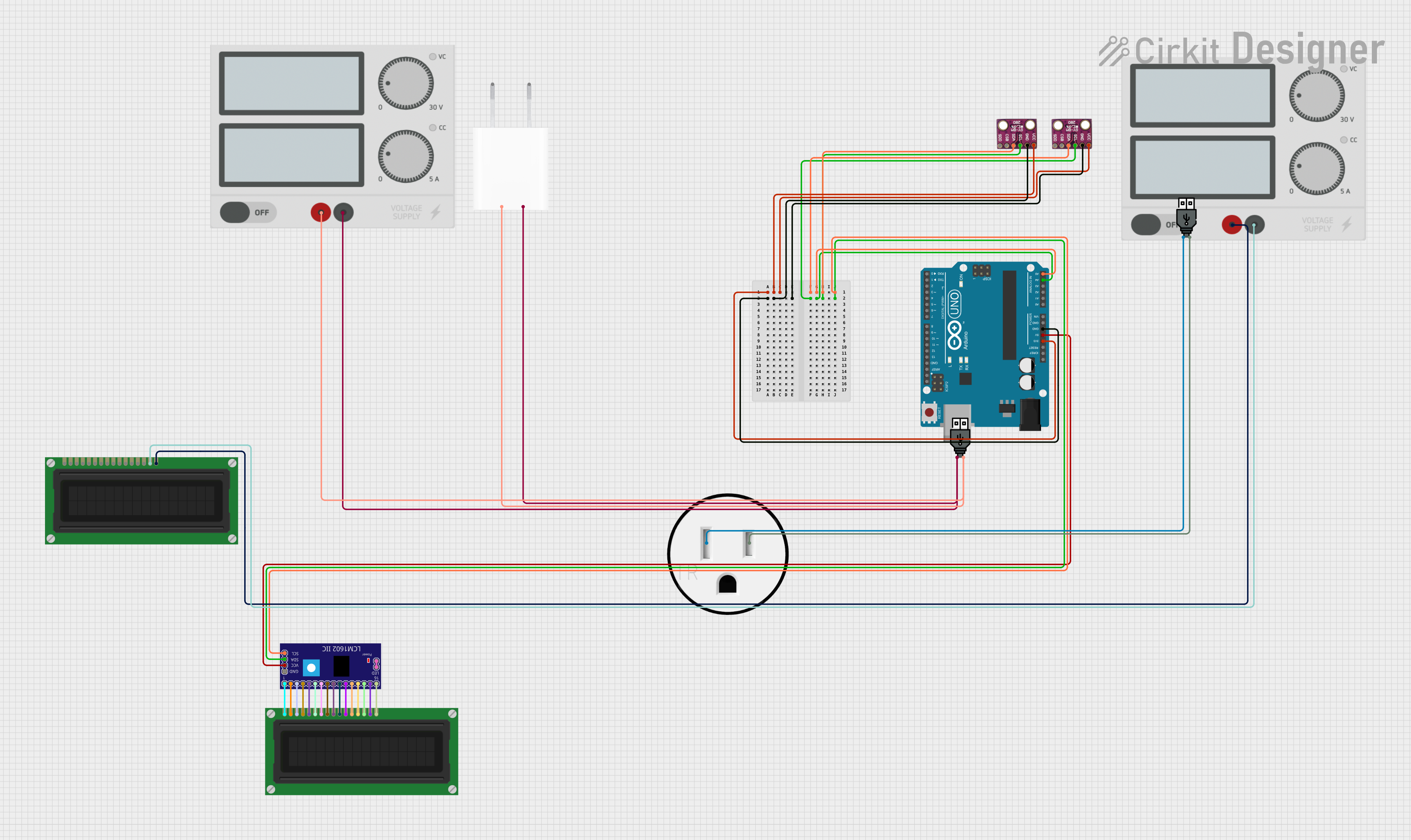
Circuit Documentation
Summary
This circuit integrates various components including an Arduino UNO microcontroller, a BMP280 sensor, an LCM1602 IIC module with an LCD display, a 5V adapter, a USB power supply, and a 120V outlet. The primary function of this circuit is to interface the BMP280 sensor and the LCD display with the Arduino UNO for data acquisition and display. The BMP280 sensor is used for measuring temperature and atmospheric pressure, while the LCM1602 IIC module controls the LCD display for output visualization. Power is supplied to the circuit through a 5V adapter and USB power sources, which are also connected to a 120V outlet for AC to DC conversion.
Component List
LCM1602 IIC
- Description: An I2C interface module for LCD displays.
- Pins: GND, VCC, SDA, SCL, D6, D7, A, K, VSS, VDD, V0, RS, D2, D3, D4, D5, RW, E, D0, D1, LED_A, LED_B
BMP280
- Description: A digital barometric pressure and temperature sensor.
- Pins: SDO, CSB, SDA, SCL, GND, VCC
USB Power
- Description: A USB power supply module.
- Pins: +, -
5V Adapter
- Description: A power adapter that converts AC to a 5V DC output.
- Pins: AC In 1, AC In 2, 5V, GND
120V Outlet
- Description: A standard 120V AC electrical outlet.
- Pins: AC Neutral, AC Hot
Power Supply
- Description: A generic power supply module.
- Pins: +, -
Arduino UNO
- Description: A microcontroller board based on the ATmega328P.
- Pins: UNUSED, IOREF, Reset, 3.3V, 5V, GND, Vin, A0, A1, A2, A3, A4, A5, SCL, SDA, AREF, D13, D12, D11, D10, D9, D8, D7, D6, D5, D4, D3, D2, D1, D0
LCD Display (16 pin)
- Description: A 16-pin liquid crystal display.
- Pins: VSS, VDD, VO, RS, R_W, E, DB0, DB1, DB2, DB3, DB4, DB5, DB6, DB7, A, K
Wiring Details
BMP280
- VCC connected to Arduino UNO 3.3V
- SDA connected to Arduino UNO A5 and LCM1602 IIC SCL
- SCL connected to Arduino UNO A4 and LCM1602 IIC SDA
- GND connected to Arduino UNO GND
LCM1602 IIC
- VCC connected to Arduino UNO 5V
- SDA connected to BMP280 SCL and Arduino UNO A4
- SCL connected to BMP280 SDA and Arduino UNO A5
- D6 connected to LCD Display (16 pin) DB6
- D7 connected to LCD Display (16 pin) DB7
- A connected to LCD Display (16 pin) A
- K connected to LCD Display (16 pin) K
- VSS connected to LCD Display (16 pin) VSS
- VDD connected to LCD Display (16 pin) VDD
- V0 connected to LCD Display (16 pin) VO
- RS connected to LCD Display (16 pin) RS
- D2 connected to LCD Display (16 pin) DB2
- D3 connected to LCD Display (16 pin) DB3
- D4 connected to LCD Display (16 pin) DB4
- D5 connected to LCD Display (16 pin) DB5
- RW connected to LCD Display (16 pin) R_W
- E connected to LCD Display (16 pin) E
- D0 connected to LCD Display (16 pin) DB0
- D1 connected to LCD Display (16 pin) DB1
- LED_A connected to LCM1602 IIC LED_B
USB Power (Instance 1)
-
- connected to 5V Adapter 5V
-
- connected to 5V Adapter GND
USB Power (Instance 2)
-
- connected to 120V Outlet AC Hot
-
- connected to 120V Outlet AC Neutral
Power Supply (Instance 1)
-
- connected to 5V Adapter 5V
-
- connected to 5V Adapter GND
Power Supply (Instance 2)
-
- connected to LCD Display (16 pin) K
-
- connected to LCD Display (16 pin) A
Arduino UNO
- 3.3V connected to BMP280 VCC
- 5V connected to LCM1602 IIC VCC
- GND connected to BMP280 GND
- A4 connected to BMP280 SCL and LCM1602 IIC SDA
- A5 connected to BMP280 SDA and LCM1602 IIC SCL
LCD Display (16 pin)
- VSS connected to LCM1602 IIC VSS
- VDD connected to LCM1602 IIC VDD
- VO connected to LCM1602 IIC V0
- RS connected to LCM1602 IIC RS
- R_W connected to LCM1602 IIC RW
- E connected to LCM1602 IIC E
- DB0 connected to LCM1602 IIC D0
- DB1 connected to LCM1602 IIC D1
- DB2 connected to LCM1602 IIC D2
- DB3 connected to LCM1602 IIC D3
- DB4 connected to LCM1602 IIC D4
- DB5 connected to LCM1602 IIC D5
- DB6 connected to LCM1602 IIC D6
- DB7 connected to LCM1602 IIC D7
- A connected to Power Supply (Instance 2) -
- K connected to Power Supply (Instance 2) +
Documented Code
Arduino UNO Code (sketch.ino)
void setup() {
  // put your setup code here, to run once:

}

void loop() {
  // put your main code here, to run repeatedly:

}
Note: The provided code is a template and does not include specific functionality. It is expected that the user will add the necessary code to interact with the BMP280 sensor and the LCD display through the LCM1602 IIC module.