
ESP32 and L298N Motor Driver Controlled Robotic System with Servo Motors
View and Edit Project In Cirkit Designer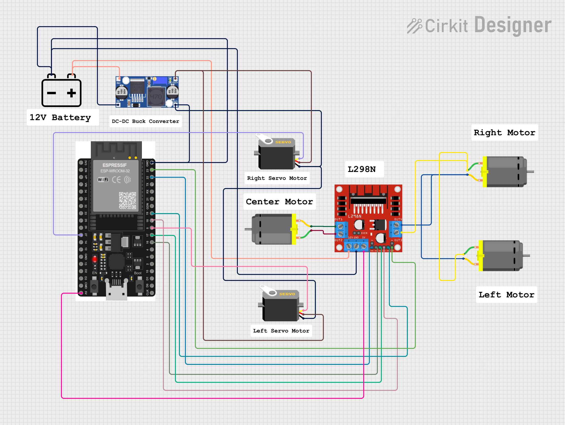
Circuit Documentation
Summary
This circuit consists of various components including servos, DC motors, a buck converter, a 12V battery, an ESP32 microcontroller, and an L298N DC motor driver. The circuit is designed to control multiple motors and servos using the ESP32 microcontroller, with power regulation provided by a buck converter and a 12V battery as the power source.
Component List
Servo
- Pins: gnd, vcc, pulse
- Description: A servo motor used for precise control of angular position.
- Purpose in Circuit: To control the angular position of a mechanical component.
DC Motor
- Pins: pin 1, pin 2
- Description: A DC motor used for continuous rotation.
- Purpose in Circuit: To provide rotational motion.
Buck Converter
- Pins: IN+, IN-, OUT+, OUT-
- Description: A DC-DC converter used to step down voltage.
- Purpose in Circuit: To regulate the voltage supplied to other components.
12V Battery
- Pins: +, -
- Description: A power source providing 12V DC.
- Purpose in Circuit: To supply power to the circuit.
ESP32 38 PINS
- Pins: GND, 23, 22/SCL, 1, 2, 21/SDA, 19, 18, 5, 17/TX2, 16/RX2, 4, 0, 15, D1, D0, CLK, 3V3, EN, VP, VN, 34, 35, 32, 33, 25, 26, 27, 14, 12, 13, D2, D3, 11, 5V/VIN
- Description: A microcontroller with Wi-Fi and Bluetooth capabilities.
- Purpose in Circuit: To control the motors and servos.
L298N DC Motor Driver
- Pins: OUT1, OUT2, 12V, GND, 5V, OUT3, OUT4, 5V-ENA-JMP-I, 5V-ENA-JMP-O, +5V-J1, +5V-J2, ENA, IN1, IN2, IN3, IN4, ENB
- Description: A dual H-bridge motor driver.
- Purpose in Circuit: To drive the DC motors.
Wiring Details
Servo
Servo 1
- gnd connected to ESP32 GND, L298N GND, Buck converter IN-, Buck converter OUT-, 12V Battery -
- vcc connected to Servo 2 vcc, Buck converter OUT+
- pulse connected to ESP32 pin 27
Servo 2
- gnd connected to ESP32 GND, L298N GND, Buck converter IN-, Buck converter OUT-, 12V Battery -
- vcc connected to Servo 1 vcc, Buck converter OUT+
- pulse connected to ESP32 pin 5
DC Motor
DC Motor 1
- pin 1 connected to L298N OUT3
- pin 2 connected to L298N OUT4
DC Motor 2
- pin 1 connected to L298N OUT3
- pin 2 connected to L298N OUT4
DC Motor 3
- pin 1 connected to L298N OUT2
- pin 2 connected to L298N OUT1
Buck Converter
- IN+ connected to L298N 12V, 12V Battery +
- IN- connected to ESP32 GND, L298N GND, Servo 1 gnd, Servo 2 gnd, Buck converter OUT-, 12V Battery -
- OUT+ connected to Servo 1 vcc, Servo 2 vcc
- OUT- connected to ESP32 GND, L298N GND, Servo 1 gnd, Servo 2 gnd, Buck converter IN-, 12V Battery -
12V Battery
- + connected to L298N 12V, Buck converter IN+
- - connected to ESP32 GND, L298N GND, Servo 1 gnd, Servo 2 gnd, Buck converter IN-, Buck converter OUT-
ESP32 38 PINS
- GND connected to Servo 1 gnd, L298N GND, Servo 2 gnd, Buck converter IN-, Buck converter OUT-, 12V Battery -
- 5V/VIN connected to L298N 5V
- 22/SCL connected to L298N ENA
- 16/RX2 connected to L298N IN1
- 17/TX2 connected to L298N IN2
- 18 connected to L298N IN3
- 19 connected to L298N IN4
- 23 connected to L298N ENB
- 27 connected to Servo 1 pulse
- 5 connected to Servo 2 pulse
L298N DC Motor Driver
- OUT1 connected to DC Motor 3 pin 2
- OUT2 connected to DC Motor 3 pin 1
- 12V connected to Buck converter IN+, 12V Battery +
- GND connected to ESP32 GND, Servo 1 gnd, Servo 2 gnd, Buck converter IN-, Buck converter OUT-, 12V Battery -
- 5V connected to ESP32 5V/VIN
- OUT3 connected to DC Motor 1 pin 1, DC Motor 2 pin 1
- OUT4 connected to DC Motor 1 pin 2, DC Motor 2 pin 2
- ENA connected to ESP32 pin 22/SCL
- IN1 connected to ESP32 pin 16/RX2
- IN2 connected to ESP32 pin 17/TX2
- IN3 connected to ESP32 pin 18
- IN4 connected to ESP32 pin 19
- ENB connected to ESP32 pin 23
Code
No code provided.