ESP32-Controlled FM Radio Transmitter
Circuit Documentation
Summary
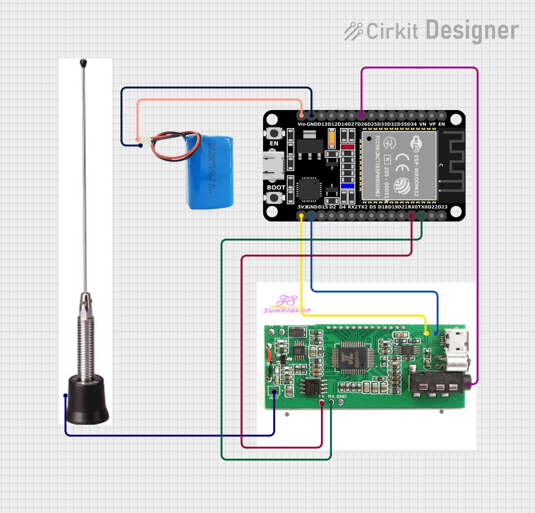
This circuit integrates an ESP32 microcontroller with a DSP PLL 87-108 MHz Stereo FM Transmitter, powered by a 5V battery. The ESP32 is responsible for controlling the FM transmitter, which can receive auxiliary input and transmit FM signals via an antenna. The ESP32 communicates with the FM transmitter through serial communication (TX/RX) and provides power to the transmitter. The antenna is connected to the FM transmitter for broadcasting purposes.
Component List
ESP32 (30 pin)
- Description: A microcontroller with WiFi and Bluetooth capabilities, featuring a wide range of GPIO pins.
- Purpose: Acts as the central processing unit of the circuit, controlling the FM transmitter and handling data communication.
DSP PLL 87-108 MHz Stereo FM Transmitter
- Description: A digital signal processing transmitter capable of broadcasting stereo FM signals.
- Purpose: Receives audio input from the ESP32 and transmits FM signals through the connected antenna.
Antenna
- Description: A device that radiates radio waves for the purpose of transmitting or receiving signals.
- Purpose: Radiates the FM signals generated by the FM transmitter.
5V Battery
- Description: A power source providing a 5V supply.
- Purpose: Powers the ESP32 microcontroller and the FM transmitter.
Wiring Details
ESP32 (30 pin)
- EN: Not connected
- VP: Not connected
- VN: Not connected
- D34-D15, D2-D4, TX2, RX2: Not connected
- D26: Connected to the "Aux in" of the FM Transmitter
- GND: Connected to the "Ground" of the FM Transmitter and the "negative" of the 5V Battery
- Vin: Connected to the "positive" of the 5V Battery
- TX0: Connected to the "Rx" of the FM Transmitter
- RX0: Connected to the "Tx" of the FM Transmitter
- 3V3: Connected to the "Vcc" of the FM Transmitter
DSP PLL 87-108 MHz Stereo FM Transmitter
- Ant in: Connected to the Antenna
- Aux in: Connected to the "D26" of the ESP32
- Mic, Usb audio in/usb power in, mono switch 2, mono switch 1: Not connected
- Ground: Connected to the "GND" of the ESP32
- Vcc: Connected to the "3V3" of the ESP32
- Rx: Connected to the "TX0" of the ESP32
- Tx: Connected to the "RX0" of the ESP32
Antenna
- Connected to the "Ant in" of the FM Transmitter
5V Battery
- positive: Connected to the "Vin" of the ESP32
- negative: Connected to the "GND" of the ESP32
Documented Code
There is no code provided for the microcontroller in this circuit. The ESP32 would typically be programmed to control the FM transmitter, handle audio input, and manage any other functions required for the specific application. Without the code, we cannot document the specific behavior or interactions of the microcontroller within this circuit.