
ESP32-C3 Mini and MCP4725 DAC Controlled Analog Output Circuit
View and Edit Project In Cirkit Designer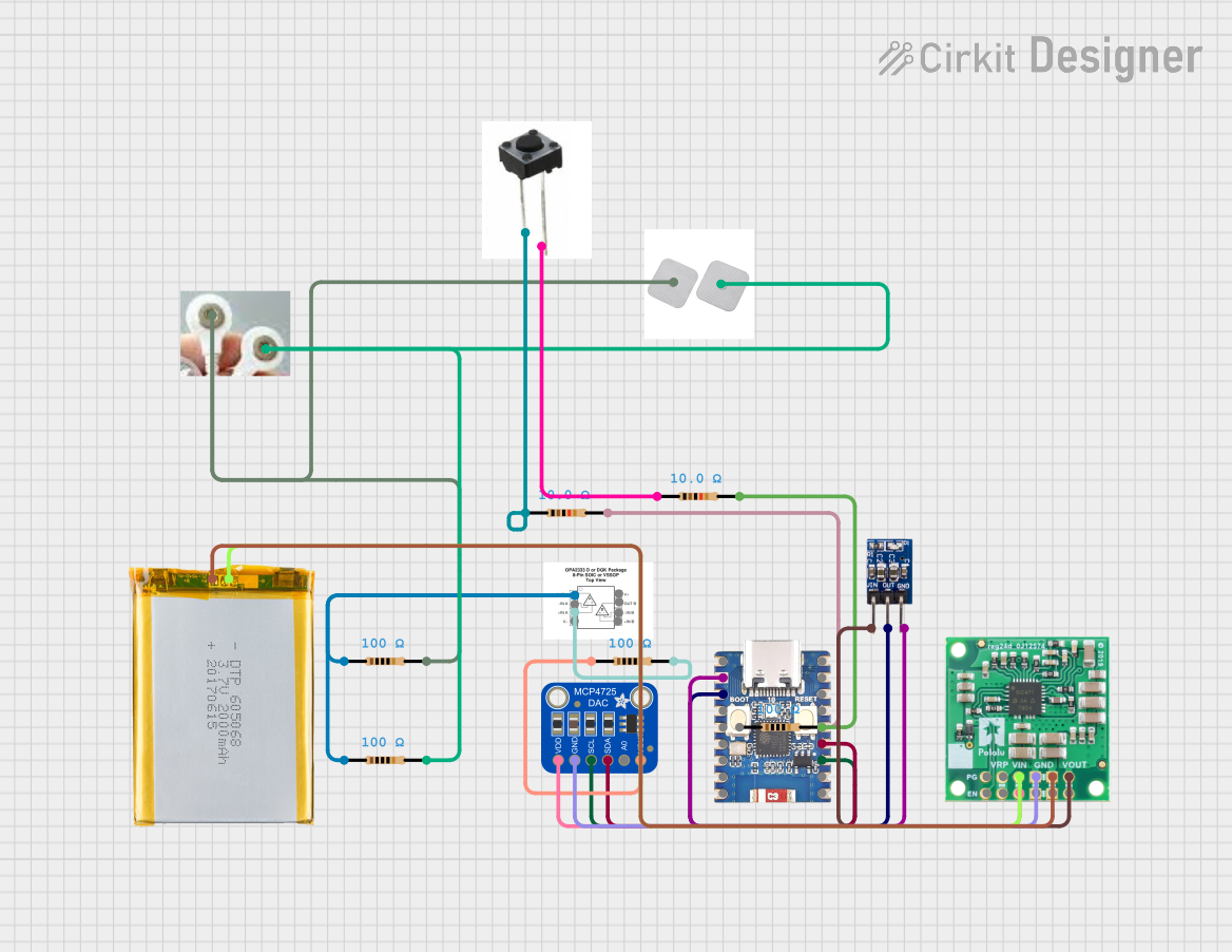
Circuit Documentation
Summary
This circuit integrates a variety of components including a microcontroller, a digital-to-analog converter (DAC), an operational amplifier (op-amp), voltage regulators, resistors, a battery, and user interface elements such as buttons and electro pads. The ESP32-C3 Mini serves as the central processing unit, interfacing with the MCP4725 DAC for analog signal output. The OPA2333AIDRGT op-amp processes the signal further, and the AMS1117 3.3 provides a stable 3.3V power supply to the ESP32-C3 Mini. A step-down voltage regulator is used to convert the battery voltage to 5V required by some components. The circuit also includes resistors for current limiting and signal conditioning, as well as buttons for user input.
Component List
ESP32-C3 Mini
- Microcontroller with WiFi and Bluetooth capabilities.
- Pins: 5V, GND, 21, 20, 3V3, 0, 1, 2, 3, 4, 5, 19, 18, 10, 9, 8, 7, 6
Adafruit MCP4725 Breakout Board - 12-Bit DAC
- A digital-to-analog converter for generating analog output signals.
- Pins: VDD, GND, SCL, SDA, A0, VOUT
OPA2333AIDRGT
- Precision low-power operational amplifier.
- Pins: OUT A, -IN A, +IN A, V-, V+, OUT B, -IN B, +IN B
AMS1117 3.3
- Low dropout voltage regulator that outputs 3.3V.
- Pins: VIN, OUT, GND
5V, 5.5A Step-Down Voltage Regulator D36V50F5
- A high-current step-down voltage regulator that outputs 5V.
- Pins: PG, EN, VRP, VIN, GND, VOUT
Resistor (100 Ohms)
- Four resistors with a resistance of 100 Ohms each.
- Pins: pin1, pin2
Resistor (10 Ohms)
- Two resistors with a resistance of 10 Ohms each.
- Pins: pin1, pin2
Electro Pads
- Conductive pads used for electrical stimulation or sensing.
- Pins: V OUT
Buttons
- User interface elements for input.
- Pins: V IN
2 Pins Button
- A simple push-button switch.
- Pins: -, +
2000mAh Battery
- A rechargeable battery providing power to the circuit.
- Pins: VCC, GND
Wiring Details
ESP32-C3 Mini
- GND connected to AMS1117 3.3 GND
- 3V3 connected to AMS1117 3.3 OUT
- Pin 10 connected to a 10 Ohm resistor
- Pin 9 (SDA) connected to MCP4725 SDA
- Pin 8 (SCL) connected to MCP4725 SCL
Adafruit MCP4725 Breakout Board - 12-Bit DAC
- VDD connected to 5V Step-Down Voltage Regulator VIN
- GND connected to 5V Step-Down Voltage Regulator GND
- SCL connected to ESP32-C3 Mini Pin 8
- SDA connected to ESP32-C3 Mini Pin 9
- VOUT connected to a 100 Ohm resistor
OPA2333AIDRGT
- OUT A connected to two 100 Ohm resistors
- +IN A connected to a 100 Ohm resistor
AMS1117 3.3
- VIN connected to 5V Step-Down Voltage Regulator VOUT
- GND connected to ESP32-C3 Mini GND
- OUT connected to ESP32-C3 Mini 3V3
5V, 5.5A Step-Down Voltage Regulator D36V50F5
- VIN connected to 2000mAh Battery VCC
- GND connected to 2000mAh Battery GND
- VOUT connected to AMS1117 3.3 VIN
Resistor (100 Ohms)
- Four resistors each with one end connected to various components as per the net list.
Resistor (10 Ohms)
- Two resistors each with one end connected to various components as per the net list.
Electro Pads
- V OUT connected to Buttons V IN and two 100 Ohm resistors.
Buttons
- V IN connected to Electro Pads V OUT and two 100 Ohm resistors.
2 Pins Button
- "+" connected to a 10 Ohm resistor
- "-" connected to a 10 Ohm resistor
2000mAh Battery
- VCC connected to 5V Step-Down Voltage Regulator VIN
- GND connected to 5V Step-Down Voltage Regulator GND
Documented Code
There is no code provided for the microcontroller in this circuit. The ESP32-C3 Mini would typically be programmed to control the DAC, read inputs from the buttons, and manage power through the voltage regulators. Without the code, the functionality of the microcontroller within this circuit cannot be documented.