
ESP32-Based Smart Weighing Scale with Proximity Sensor and Pneumatic Control
View and Edit Project In Cirkit Designer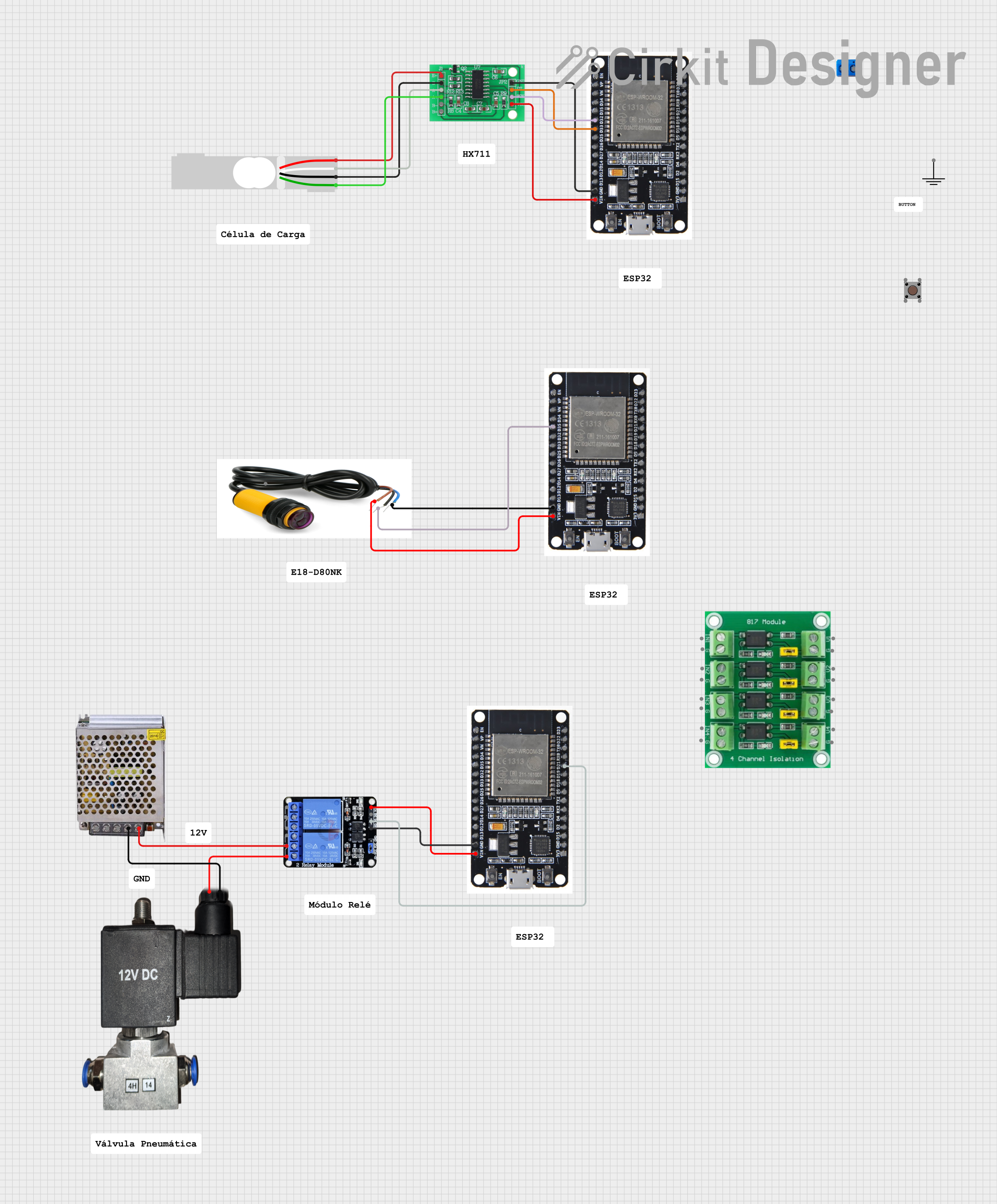
Circuit Documentation
Summary
This circuit involves an ESP32 microcontroller interfacing with various components including an HX711 load cell amplifier, a load cell, a two-channel relay, a 12V pneumatic solenoid valve, an E18-D80NK proximity sensor, and a 12V power supply. The ESP32 reads data from the load cell via the HX711 and controls the relay to operate the solenoid valve. Additionally, the ESP32 reads proximity data from the E18-D80NK sensor.
Component List
ESP32
- Description: A powerful microcontroller with Wi-Fi and Bluetooth capabilities.
- Pins: EN, VP, VN, D34, D35, D32, D33, D25, D26, D27, D14, D12, D13, GND, VIN, 3V3, D15, D2, D4, RX2, TX2, D5, D18, D19, D21, RX0, TX0, D22, D23, BOOT
Pushbutton
- Description: A simple pushbutton switch.
- Pins: Pin 3 (out), Pin 4 (out), Pin 1 (in), Pin 2 (in)
HX711 - Bridge Sensor Interface
- Description: A precision 24-bit analog-to-digital converter (ADC) designed for weigh scales and industrial control applications.
- Pins: E+, E-, A-, A+, B-, B+, GND - GROUND, DATA (OUT), SCK - CLOCK (IN), 3.3/3.5V Supply
Load Cell - Red/white/black/green
- Description: A sensor used to measure weight or force.
- Pins: E+, A-, E-, A+
GND
- Description: Ground connection.
- Pins: GND
Two Channel Relay 5v
- Description: A relay module that allows control of high voltage devices.
- Pins: VCC, IN2, IN1, GND, NC2, C2, NO2, NC1, C1, NO1
E18-D80NK
- Description: An infrared proximity sensor.
- Pins: VCC, GND, DATA
12v Pneumatic solenoid valve
- Description: A valve controlled by a 12V signal to regulate air flow.
- Pins: VCC, GND
POWER SUPPLY 12V 5AMP
- Description: A power supply providing 12V DC output.
- Pins: 220V Positive Pole (AC), 220V Negative Pole (AC), GND, GND (DC), 12V-24V Output (DC)
Modulo 817
- Description: A module with multiple input and output channels.
- Pins: IN1, G, IN2, IN3, IN4, UOUT1, UOUT2, UOUT3, UOUT4
Wiring Details
ESP32
- D32 connected to SCK - CLOCK (IN) of HX711 - Bridge Sensor Interface
- D33 connected to DATA (OUT) of HX711 - Bridge Sensor Interface
- GND connected to GND - GROUND of HX711 - Bridge Sensor Interface
- VIN connected to 3.3/3.5V Supply of HX711 - Bridge Sensor Interface
- VIN connected to VCC of Two Channel Relay 5v
- D21 connected to IN1 of Two Channel Relay 5v
- GND connected to GND of Two Channel Relay 5v
- D35 connected to DATA of E18-D80NK
- GND connected to GND of E18-D80NK
- VIN connected to VCC of E18-D80NK
HX711 - Bridge Sensor Interface
- SCK - CLOCK (IN) connected to D32 of ESP32
- DATA (OUT) connected to D33 of ESP32
- GND - GROUND connected to GND of ESP32
- 3.3/3.5V Supply connected to VIN of ESP32
- E+ connected to E+ of Load Cell - Red/white/black/green
- E- connected to E- of Load Cell - Red/white/black/green
- A- connected to A- of Load Cell - Red/white/black/green
- A+ connected to A+ of Load Cell - Red/white/black/green
Load Cell - Red/white/black/green
- E+ connected to E+ of HX711 - Bridge Sensor Interface
- E- connected to E- of HX711 - Bridge Sensor Interface
- A- connected to A- of HX711 - Bridge Sensor Interface
- A+ connected to A+ of HX711 - Bridge Sensor Interface
Two Channel Relay 5v
- VCC connected to VIN of ESP32
- IN1 connected to D21 of ESP32
- GND connected to GND of ESP32
- C1 connected to 12V-24V Output (DC) of POWER SUPPLY 12V 5AMP
- NO1 connected to VCC of 12v Pneumatic solenoid valve
E18-D80NK
- DATA connected to D35 of ESP32
- GND connected to GND of ESP32
- VCC connected to VIN of ESP32
12v Pneumatic solenoid valve
- VCC connected to NO1 of Two Channel Relay 5v
- GND connected to GND (DC) of POWER SUPPLY 12V 5AMP
POWER SUPPLY 12V 5AMP
- 12V-24V Output (DC) connected to C1 of Two Channel Relay 5v
- GND (DC) connected to GND of 12v Pneumatic solenoid valve
Code Documentation
Code for ESP32 (Instance 1)
/*
     Q0481-Sketch-Calibrar
     AUTOR:   BrincandoComIdeias
     LINK:    https://www.youtube.com/brincandocomideias ; https://cursodearduino.net/
     COMPRE:  https://www.arducore.com.br/
     SKETCH:  Calibrar Balanca com módulo HX711
     DATA:    04/07/2019
*/

// INCLUSÃO DE BIBLIOTECAS
#include <HX711.h>

// DEFINIÇÕES DE PINOS
#define pinDT  33
#define pinSCK  32
#define pinBotao 4

// INSTANCIANDO OBJETOS
HX711 scale;

// DECLARAÇÃO DE VARIÁVEIS
float medida = 0;

void setup() {
  Serial.begin(57600);

  scale.begin(pinDT, pinSCK); // CONFIGURANDO OS PINOS DA BALANÇA
  scale.set_scale(); // LIMPANDO O VALOR DA ESCALA

  delay(2000);
  scale.tare(); // ZERANDO A BALANÇA PARA DESCONSIDERAR A MASSA DA ESTRUTURA

  Serial.println("Balança Zerada");
}

void loop() {

  medida = scale.get_units(5); // SALVANDO NA VARIAVEL O VALOR DA MÉDIA DE 5 MEDIDAS
  Serial.println(medida, 3); // ENVIANDO PARA MONITOR SERIAL A MEDIDA COM 3 CASAS DECIMAIS

  scale.power_down(); // DESLIGANDO O SENSOR
  delay(1000); // AGUARDA 5 SEGUNDOS
  scale.power_up(); // LIGANDO O SENSOR
}
Code for ESP32 (Instance 2)
// Define the digital input pin where the sensor is connected
const int proximitySensorPin = 35;

void setup() {
  // Initialize the proximitySensorPin as an input
  pinMode(proximitySensorPin, INPUT);
  Serial.begin(9600); // Start serial communication at 9600 baud rate
}

void loop() {
  // Read the state of the proximity sensor
  int sensorState = digitalRead(proximitySensorPin);

  // Check if the sensor is detecting an object
  if (sensorState == HIGH) {
    Serial.println("Object Detected");
  } else {
    Serial.println("No Object Detected");
  }

  // Wait for 100 milliseconds before reading again
  delay(100);
}
This documentation provides a comprehensive overview of the circuit, including a summary, detailed component list, wiring details, and documented code for the microcontrollers.