Cirkit Designer
Your all-in-one circuit design IDE
Home /
Project Documentation
Arduino UNO Motion-Activated LED and Buzzer System with Battery Power
Circuit Documentation
Summary
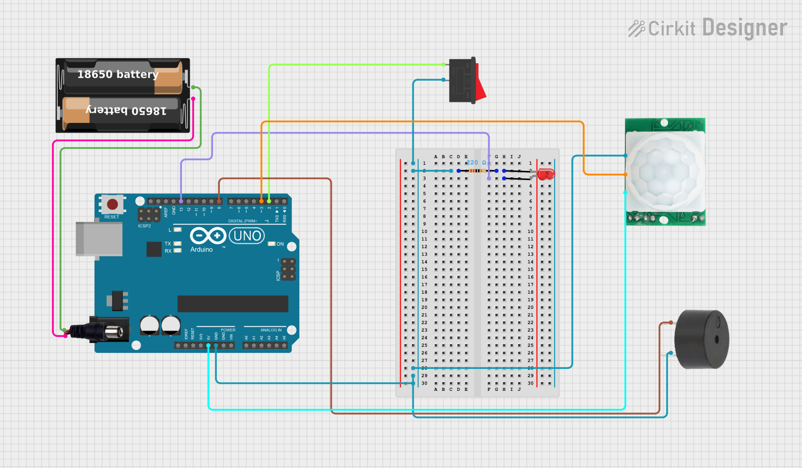
This document provides a detailed overview of a circuit that includes an Arduino UNO microcontroller, a red LED, a rocker switch, a buzzer, a power jack, a battery case, a resistor, and an HC-SR501 motion sensor. The circuit is designed to control the LED and buzzer based on the input from the motion sensor and the rocker switch.
Component List
Arduino UNO
- Description: A microcontroller board based on the ATmega328P.
- Pins: UNUSED, IOREF, Reset, 3.3V, 5V, GND, Vin, A0, A1, A2, A3, A4, A5, SCL, SDA, AREF, D13, D12, D11, D10, D9, D8, D7, D6, D5, D4, D3, D2, D1, D0
LED: Two Pin (red)
- Description: A red light-emitting diode.
- Pins: cathode, anode
Rocker Switch
- Description: A switch that can toggle between two states.
- Pins: 1, 2
Buzzer
- Description: A piezoelectric buzzer.
- Pins: PIN, GND
Power Jack
- Description: A jack for connecting a power source.
- Pins: POSITIF, NEGATIF
Battery Case
- Description: A case for holding batteries.
- Pins: +, -
Resistor
- Description: A 220 Ohm resistor.
- Pins: pin1, pin2
- Properties: Resistance = 220 Ohms
HC-SR501 Motion Sensor
- Description: A motion sensor module.
- Pins: GND, OUT, VCC
Wiring Details
Arduino UNO
- 5V is connected to VCC of the HC-SR501 Motion Sensor.
- GND is connected to:
- Pin 2 of the Rocker Switch
- GND of the Buzzer
- Pin 1 of the Resistor
- GND of the HC-SR501 Motion Sensor
- D13 is connected to the anode of the LED.
- D8 is connected to the PIN of the Buzzer.
- D3 is connected to the OUT of the HC-SR501 Motion Sensor.
- D2 is connected to Pin 1 of the Rocker Switch.
LED: Two Pin (red)
- Anode is connected to D13 of the Arduino UNO.
- Cathode is connected to Pin 2 of the Resistor.
Rocker Switch
- Pin 1 is connected to D2 of the Arduino UNO.
- Pin 2 is connected to GND of the Arduino UNO.
Buzzer
- PIN is connected to D8 of the Arduino UNO.
- GND is connected to GND of the Arduino UNO.
Power Jack
- POSITIF is connected to + of the Battery Case.
- NEGATIF is connected to - of the Battery Case.
Battery Case
- + is connected to POSITIF of the Power Jack.
- - is connected to NEGATIF of the Power Jack.
Resistor
- Pin 1 is connected to GND of the Arduino UNO.
- Pin 2 is connected to the cathode of the LED.
HC-SR501 Motion Sensor
- VCC is connected to 5V of the Arduino UNO.
- GND is connected to GND of the Arduino UNO.
- OUT is connected to D3 of the Arduino UNO.
Documented Code
Arduino UNO Code (sketch.ino)
void setup() {
  // put your setup code here, to run once:

}

void loop() {
  // put your main code here, to run repeatedly:

}
Additional Documentation (documentation.txt)
This document provides a comprehensive overview of the circuit, including the components used, their wiring details, and the code for the Arduino UNO microcontroller.