
Arduino Mega Controlled Multi-Stepper Motor System with WiFi and RF Communication
View and Edit Project In Cirkit Designer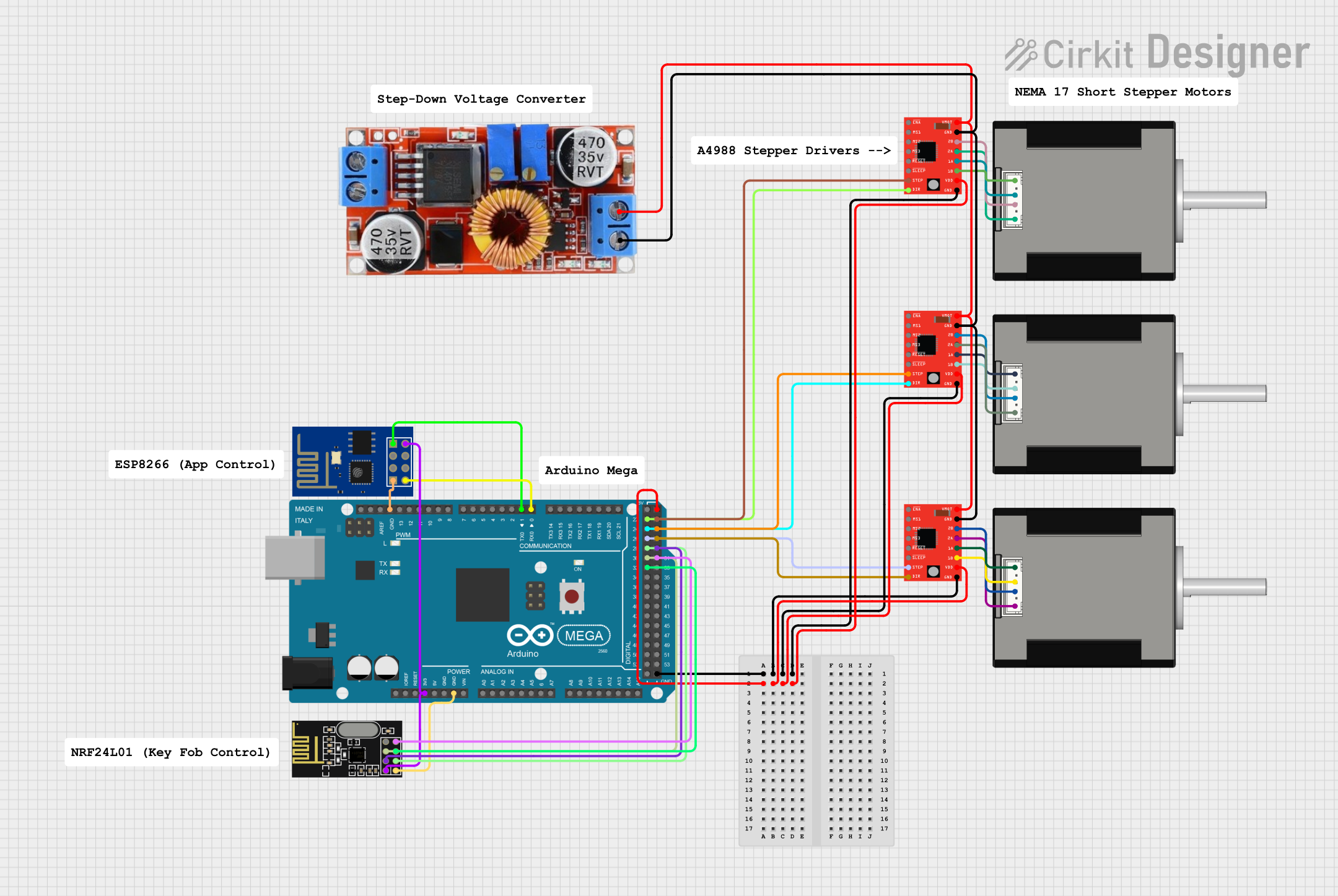
Circuit Documentation
Summary
This circuit is designed to control multiple Nema 17 stepper motors using A4988 stepper motor drivers. It is controlled by an Arduino Mega 2560, which sends step and direction signals to the drivers. The circuit also includes a step-down voltage regulator to provide the necessary voltage to the motor drivers and an ESP8266 ESP-01 WiFi module and NRF24L01 module for wireless communication capabilities.
Component List
Microcontrollers
- Arduino Mega 2560: A microcontroller board based on the ATmega2560, with a large number of IO pins, including digital, analog, and PWM, as well as I2C, SPI, and UART communication capabilities.
Motor Drivers
- A4988 Stepper Motor Driver (Red): A complete microstepping motor driver with a built-in translator for easy operation.
Motors
- Nema 17 42-STH48: A stepper motor with a 1.8-degree step angle, suitable for a wide range of applications.
Voltage Regulators
- Regulator Stepdown DC XL4015 CC CV: A buck converter capable of stepping down voltage with constant current and constant voltage control.
Wireless Modules
- ESP8266 ESP-01 WiFi Module: A self-contained SOC with integrated TCP/IP protocol stack that can give any microcontroller access to a WiFi network.
- NRF24L01: A wireless transceiver module that operates in the 2.4GHz band, suitable for adding wireless capability to a project.
Miscellaneous
- Comments: Placeholder components for additional notes or documentation.
Wiring Details
Arduino Mega 2560
- Digital pins D26, D27, D22, D23, D24, D25, D28, D29, D30, D31, D32 are used to interface with the A4988 stepper motor drivers and the NRF24L01 module.
- The 5V pin provides power to the A4988 stepper motor drivers' VDD pins.
- The 3V3 pin provides power to the ESP8266 ESP-01 WiFi Module and NRF24L01 module.
- The GND pins are connected to the ground pins of all components to complete the circuits.
A4988 Stepper Motor Drivers
- STEP and DIR pins are controlled by the Arduino Mega 2560 to operate the stepper motors.
- VMOT pins are connected to the output of the voltage regulator to receive motor power.
- GND pins are connected to the ground for power and signal reference.
- VDD pins are connected to the 5V output from the Arduino Mega 2560 for logic power.
- 1A, 1B, 2A, 2B pins are connected to the corresponding pins on the Nema 17 stepper motors to drive the coils.
Nema 17 42-STH48 Stepper Motors
- A1 Green, A2 (black), B1 Blue, B2 Red pins are connected to the corresponding outputs on the A4988 stepper motor drivers to receive control signals for movement.
Regulator Stepdown DC XL4015 CC CV
- IN +, IN - pins are connected to the input power source.
- OUT +, OUT - pins provide the regulated voltage to the VMOT pins of the A4988 stepper motor drivers.
ESP8266 ESP-01 WiFi Module
- VCC is connected to the 3V3 output from the Arduino Mega 2560.
- GND is connected to the ground.
- TXD, RXD are connected to the RX0, TX0 pins of the Arduino Mega 2560 for serial communication.
NRF24L01
- VCC (3V) is connected to the 3V3 output from the Arduino Mega 2560.
- GND is connected to the ground.
- CE, CSN, SCK, MOSI, MISO pins are connected to the corresponding SPI pins on the Arduino Mega 2560 for communication.
Documented Code
Arduino Mega 2560 Code (sketch.ino)
void setup() {
  // put your setup code here, to run once:

}

void loop() {
  // put your main code here, to run repeatedly:

}
Additional Notes (documentation.txt)
No additional code documentation provided.