
Battery-Powered IR Sensor Alarm with LED Indicator and Buzzer
View and Edit Project In Cirkit Designer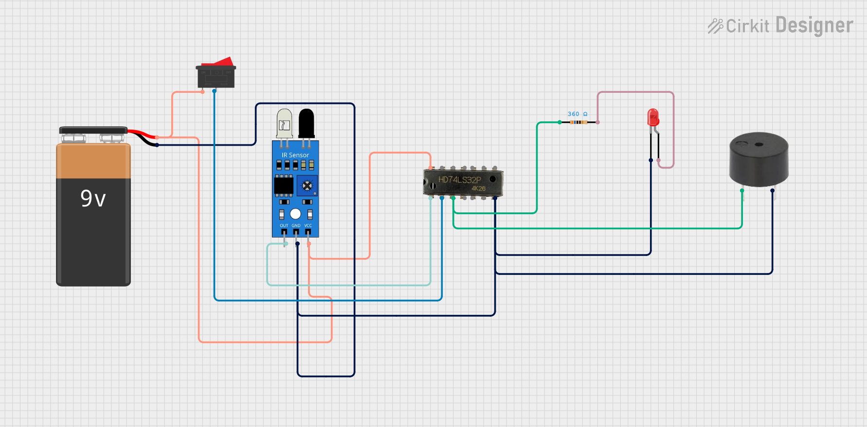
Circuit Documentation
Summary
This document provides a detailed description of a circuit that includes an IR sensor, a 9V battery, a buzzer, a rocker switch, a red LED, a resistor, and a 7432 OR Gate IC. The circuit is designed to detect an IR signal and activate a buzzer and an LED based on the logic processed by the OR Gate IC.
Component List
IR Sensor
- Pins: out, gnd, vcc
- Description: An infrared sensor used to detect IR signals.
- Purpose in Circuit: Detects IR signals and sends the output to the OR Gate IC.
9V Battery
- Pins: -, +
- Description: A 9V power source.
- Purpose in Circuit: Provides power to the entire circuit.
Buzzer
- Pins: PIN, GND
- Description: An electronic device that emits sound.
- Purpose in Circuit: Produces an audible alert when activated.
Rocker Switch
- Pins: 1, 2
- Description: A switch used to control the power supply.
- Purpose in Circuit: Turns the circuit on and off.
LED: Two Pin (red)
- Pins: cathode, anode
- Description: A red light-emitting diode.
- Purpose in Circuit: Provides a visual indication when activated.
Resistor
- Pins: pin1, pin2
- Description: A 360 Ohms resistor.
- Purpose in Circuit: Limits the current flowing through the LED.
7432 OR Gate IC
- Pins: A1, B1, Y1, A2, B2, Y2, GND, VCC, B4, A4, Y4, B3, A3, Y3
- Description: A quad 2-input OR gate IC.
- Purpose in Circuit: Processes the input signals and provides the output based on OR logic.
Wiring Details
IR Sensor
- out connected to A1 of 7432 OR Gate IC
- gnd connected to - of 9V Battery
- vcc connected to 1 of Rocker Switch
9V Battery
- - connected to GND of 7432 OR Gate IC, GND of Buzzer, gnd of IR Sensor, and cathode of LED: Two Pin (red)
- + connected to 1 of Rocker Switch
Buzzer
- PIN connected to pin1 of Resistor
- GND connected to - of 9V Battery
Rocker Switch
- 1 connected to + of 9V Battery
- 2 connected to B1 of 7432 OR Gate IC
LED: Two Pin (red)
- cathode connected to - of 9V Battery
- anode connected to pin2 of Resistor
Resistor
- pin1 connected to Y1 of 7432 OR Gate IC
- pin2 connected to anode of LED: Two Pin (red)
7432 OR Gate IC
- A1 connected to out of IR Sensor
- B1 connected to 2 of Rocker Switch
- Y1 connected to pin1 of Resistor
- GND connected to - of 9V Battery
- VCC connected to 1 of Rocker Switch
Code
There is no code associated with this circuit.