
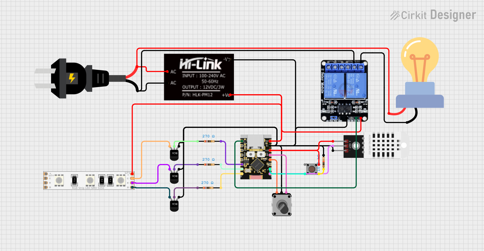
Circuit Documentation
Summary
This document provides a detailed overview of a circuit that includes an ESP32C3 microcontroller, a DHT22 temperature and humidity sensor, an RGB LED strip, a pushbutton, a rotary encoder, several NPN transistors, resistors, an AC source, an HLK-PM12 power module, an AC LED bulb, and a two-channel relay. The circuit is designed to control the RGB LED strip and the AC LED bulb based on inputs from the pushbutton and rotary encoder, with temperature and humidity data being read from the DHT22 sensor.
Component List
ESP32C3 Supermini
- Description: Microcontroller
- Pins: GPIO05, GPIO06, GPIO07, GPIO08, GPIO09, GPIO10, GPIO20, GPIO21, GPIO00, GPIO01, GPIO02, GPIO03, GPIO04, 3.3V, GND, +5V
DHT22
- Description: Temperature and Humidity Sensor
- Pins: +, Out, -
LED RGB Strip
- Description: RGB LED Strip
- Pins: Common Connect, Blue Connect, Red Connect, Green Connect
Pushbutton
- Description: Pushbutton
- Pins: Pin 3 (out), Pin 4 (out), Pin 1 (in), Pin 2 (in)
Rotary Encoder
- Description: Rotary Encoder
- Pins: EncoderPinA (output pin A), EncoderPinC (common), EncoderPinB (output pin B)
NPN-Transistor
- Description: NPN Transistor
- Pins: E, C, B
Resistor (270 Ohms)
- Description: Resistor
- Pins: pin1, pin2
- Properties: Resistance: 270 Ohms
Resistor (10k Ohms)
- Description: Resistor
- Pins: pin1, pin2
- Properties: Resistance: 10k Ohms
AC Source
- Description: AC Power Source
- Pins: -, +
HLK-PM12
- Description: Power Module
- Pins: +V0, -V0, AC
LED bulb AC / Bombillo AC
- Description: AC LED Bulb
- Pins: +, -
Two Channel Relay 5v
- Description: Relay Module
- Pins: VCC, IN2, IN1, GND, NC2, C2, NO2, NC1, C1, NO1
Wiring Details
ESP32C3 Supermini
- GPIO05 connected to Two Channel Relay 5v IN2
- GPIO10 connected to Resistor pin2 (270 Ohms)
- GPIO20 connected to Resistor pin2 (270 Ohms)
- GPIO21 connected to Resistor pin2 (270 Ohms)
- GPIO00 connected to DHT22 Out
- GPIO01 connected to Pushbutton Pin 1 (in)
- GPIO03 connected to Rotary Encoder EncoderPinB (output pin B)
- GPIO04 connected to Rotary Encoder EncoderPinA (output pin A)
- 3.3V connected to DHT22 + and Pushbutton Pin 4 (out)
- GND connected to HLK-PM12 -V0, NPN-Transistor E, DHT22 -, Rotary Encoder EncoderPinC (common), Resistor pin2 (10k Ohms), Two Channel Relay 5v GND
DHT22
- Out connected to ESP32C3 Supermini GPIO00
- + connected to ESP32C3 Supermini 3.3V
- - connected to HLK-PM12 -V0
LED RGB Strip
- Common Connect connected to HLK-PM12 +V0
- Blue Connect connected to NPN-Transistor B
- Red Connect connected to NPN-Transistor B
- Green Connect connected to NPN-Transistor B
Pushbutton
- Pin 1 (in) connected to ESP32C3 Supermini GPIO01
- Pin 2 (in) connected to Resistor pin1 (10k Ohms)
- Pin 4 (out) connected to ESP32C3 Supermini 3.3V
Rotary Encoder
- EncoderPinA (output pin A) connected to ESP32C3 Supermini GPIO04
- EncoderPinB (output pin B) connected to ESP32C3 Supermini GPIO03
- EncoderPinC (common) connected to HLK-PM12 -V0
NPN-Transistor
- E connected to HLK-PM12 -V0
- B connected to LED RGB Strip Blue Connect
- B connected to LED RGB Strip Red Connect
- B connected to LED RGB Strip Green Connect
- C connected to Resistor pin1 (270 Ohms)
Resistor (270 Ohms)
- pin1 connected to NPN-Transistor C
- pin2 connected to ESP32C3 Supermini GPIO10
- pin2 connected to ESP32C3 Supermini GPIO20
- pin2 connected to ESP32C3 Supermini GPIO21
Resistor (10k Ohms)
- pin1 connected to Pushbutton Pin 2 (in)
- pin2 connected to HLK-PM12 -V0
AC Source
- - connected to HLK-PM12 AC
- + connected to HLK-PM12 AC
HLK-PM12
- +V0 connected to ESP32C3 Supermini +5V, Two Channel Relay 5v VCC, LED RGB Strip Common Connect
- -V0 connected to ESP32C3 Supermini GND, NPN-Transistor E, DHT22 -, Rotary Encoder EncoderPinC (common), Resistor pin2 (10k Ohms), Two Channel Relay 5v GND
- AC connected to AC Source -, AC Source +
LED bulb AC / Bombillo AC
- + connected to HLK-PM12 AC
- - connected to Two Channel Relay 5v NC2
Two Channel Relay 5v
- IN2 connected to ESP32C3 Supermini GPIO05
- GND connected to HLK-PM12 -V0
- VCC connected to HLK-PM12 +V0
- C2 connected to AC Source +
- NC2 connected to LED bulb AC / Bombillo AC -
Documented Code
ESP32C3 Supermini Code
void setup() {
  // put your setup code here, to run once:

}

void loop() {
  // put your main code here, to run repeatedly:

}
DHT22 Code
void setup() {
  // put your setup code here, to run once:

}

void loop() {
  // put your main code here, to run repeatedly:

}
This documentation provides a comprehensive overview of the circuit, including the components used, their connections, and the code for the microcontrollers.