ESP32-CAM Controlled Traffic Light System with Servo Actuation
Circuit Documentation
Summary
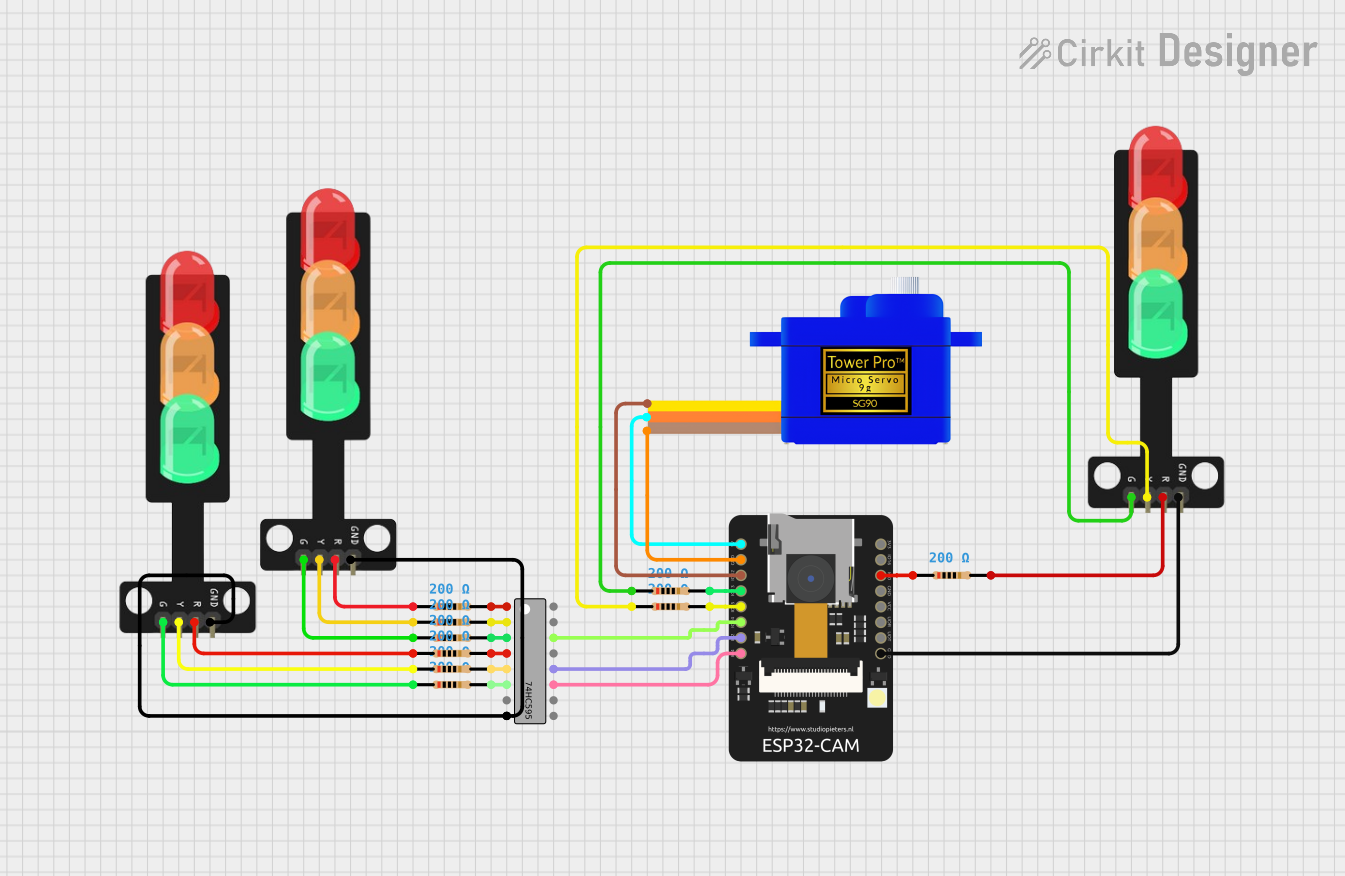
This circuit integrates an ESP32-CAM module with a servomotor (SG90), two traffic lights, and a 74HC595 shift register. The ESP32-CAM controls the servomotor and the traffic lights through GPIO pins, with the 74HC595 shift register expanding the output capabilities for driving multiple traffic light LEDs. The circuit also includes several resistors to limit current to the LEDs of the traffic lights.
Component List
ESP32-CAM
- Description: A microcontroller module with Wi-Fi and camera capabilities.
- Pins: 5V, GND, IO12, IO13, IO15, IO14, IO2, IO4, VOT, VOR, VCC, IO0, IO16, 3V3
Traffic Light
- Description: A module with three LEDs representing the green, yellow, and red lights of a traffic signal.
- Pins: Green, Yellow, Red, GND
Servomotor SG90
- Description: A small and lightweight servomotor for precision movement.
- Pins: SIG, VCC, GND
74HC595 Shift Register
- Description: An 8-bit serial-in, serial or parallel-out shift register with output latches.
- Pins: Q1-Q7, GND, VCC, Q0, DS (DATA), OE (Enable), ST_CP (RCLK), SH_CP (SRCLK), MR (SRCLR), Q7' (QH)
Resistor (200 Ohms)
- Description: A resistor with a resistance of 200 Ohms, used for current limiting.
- Pins: pin1, pin2
Wiring Details
ESP32-CAM
- 5V connected to Servomotor SG90 VCC
- GND connected to Servomotor SG90 GND, Traffic Light GND, and 74HC595 GND
- IO12 connected to Servomotor SG90 SIG
- IO13 connected to Resistor (pin2)
- IO15 connected to Resistor (pin2)
- IO14 connected to 74HC595 DS (DATA)
- IO2 connected to 74HC595 ST_CP (RCLK)
- IO4 connected to 74HC595 SH_CP (SRCLK)
- IO0 connected to Resistor (pin1)
Traffic Light (Instance 1)
- Green connected to Resistor (pin1)
- Yellow connected to Resistor (pin1)
- Red connected to Resistor (pin1)
- GND connected to ESP32-CAM GND
Traffic Light (Instance 2)
- Green connected to Resistor (pin1)
- Yellow connected to Resistor (pin1)
- Red connected to Resistor (pin1)
- GND connected to 74HC595 GND
Traffic Light (Instance 3)
- Green connected to Resistor (pin1)
- Yellow connected to Resistor (pin2)
- Red connected to Resistor (pin2)
- GND connected to ESP32-CAM GND
Servomotor SG90
- SIG connected to ESP32-CAM IO12
- VCC connected to ESP32-CAM 5V
- GND connected to ESP32-CAM GND
74HC595 Shift Register
- DS (DATA) connected to ESP32-CAM IO14
- ST_CP (RCLK) connected to ESP32-CAM IO2
- SH_CP (SRCLK) connected to ESP32-CAM IO4
- GND connected to ESP32-CAM GND and Traffic Light GND
- Q1-Q6 connected to respective Resistor (pin2)
Resistor (200 Ohms)
- pin1 connected to respective Traffic Light LED pin or ESP32-CAM IO0
- pin2 connected to respective 74HC595 Qx output or ESP32-CAM IOx
Documented Code
No code was provided for the microcontrollers in the circuit. The documentation of the code would typically include a description of the functionality implemented in the code, such as control algorithms, communication protocols, or signal processing. It would also include comments within the code to explain the purpose of each function, variable, and significant block of code. Since no code is available, this section remains empty.