
Arduino-Controlled PIR Motion Sensor with Stepper Motor Actuation
View and Edit Project In Cirkit Designer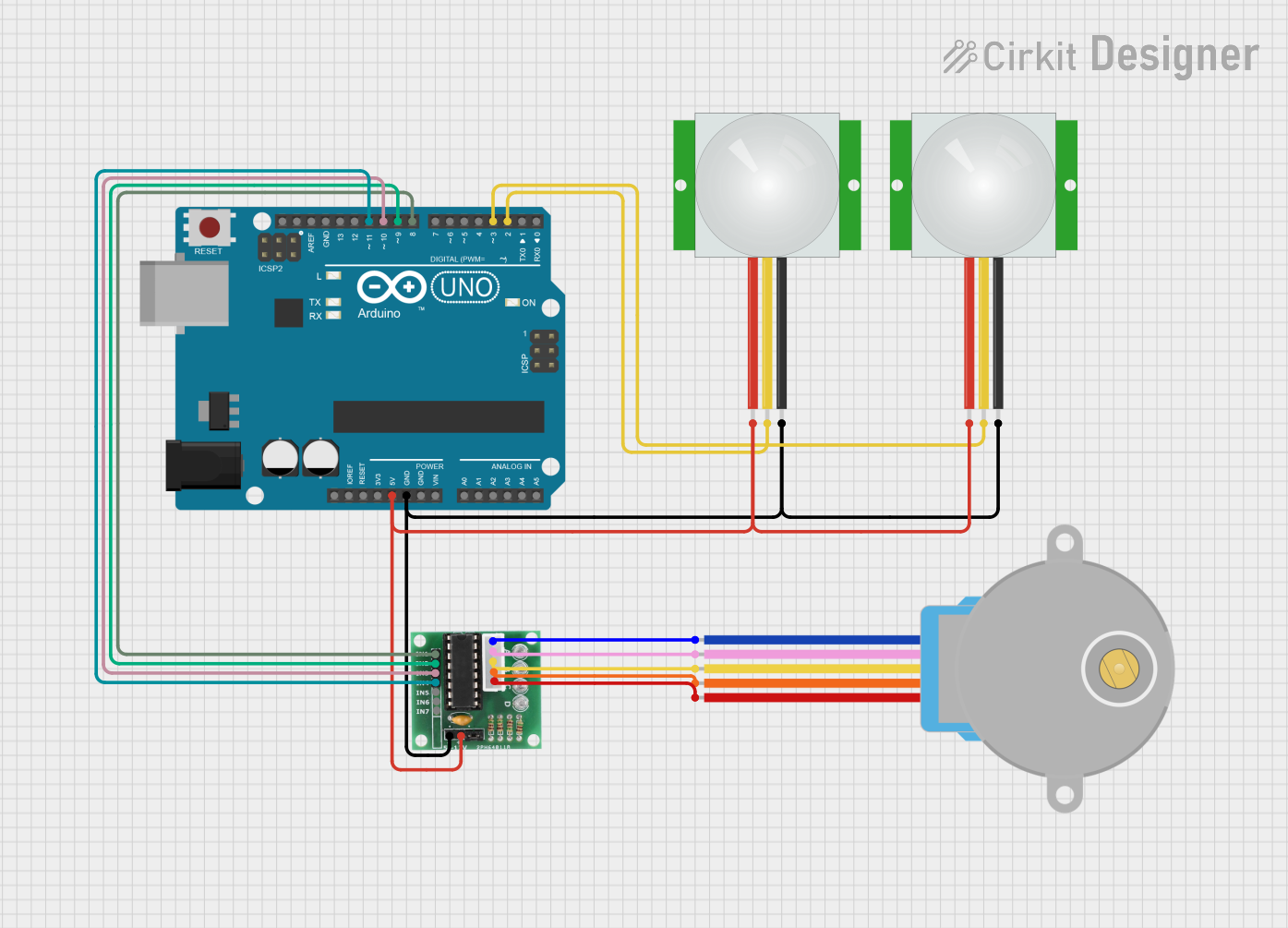
Circuit Documentation
Summary
This circuit integrates an Arduino UNO microcontroller with a 28BYJ-48 Stepper Motor, a ULN2003 driver module, and two PIR sensors. The Arduino UNO is responsible for controlling the stepper motor via the ULN2003 driver and for processing signals from the PIR sensors. The stepper motor is used for precise motion control, and the PIR sensors are used to detect motion in the environment. The ULN2003 driver module interfaces between the Arduino and the stepper motor, providing the necessary current and voltage levels. The circuit is powered by the 5V output from the Arduino UNO, which also provides ground connections to the other components.
Component List
Arduino UNO
- Microcontroller board based on the ATmega328P
- Provides digital I/O pins, analog input pins, and various power outputs
- Used as the central controller for the circuit
28BYJ-48 Stepper Motor
- A small, 5-wire, unipolar stepper motor
- Used for precise motion control in the circuit
ULN2003 Driver Module
- A 7-channel Darlington array that can drive high current loads
- Interfaces between the Arduino and the stepper motor
PIR Sensor
- Passive Infrared sensor used to detect motion
- Two instances of this sensor are used in the circuit for motion detection
Wiring Details
Arduino UNO
5Vpin provides power to the ULN2003 driver module and both PIR sensorsGNDpin is connected to the ground of the ULN2003 driver module and both PIR sensors- Digital pins
D8,D9,D10, andD11are connected to theIN1,IN2,IN3, andIN4inputs of the ULN2003, respectively - Digital pins
D2andD3are connected to theSIGoutputs of the PIR sensors
28BYJ-48 Stepper Motor
BLUE,PINK,YELLOW,ORANGE, andREDwires are connected to theCOIL1,COIL2,COIL3,COIL4, andCOIL5outputs of the ULN2003, respectively
ULN2003 Driver Module
+pin is connected to the5Voutput of the Arduino UNOGNDpin is connected to theGNDpin of the Arduino UNOIN1,IN2,IN3, andIN4inputs are connected to theD8,D9,D10, andD11pins of the Arduino UNO, respectivelyCOIL1,COIL2,COIL3,COIL4, andCOIL5outputs are connected to the corresponding wires of the 28BYJ-48 Stepper Motor
PIR Sensors
VDDpins are connected to the5Voutput of the Arduino UNOGNDpins are connected to theGNDpin of the Arduino UNOSIGoutputs are connected to theD2andD3pins of the Arduino UNO
Documented Code
Arduino UNO Code (sketch.ino)
void setup() {
  // put your setup code here, to run once:

}

void loop() {
  // put your main code here, to run repeatedly:

}
The provided code is a template and does not contain any functional code for controlling the stepper motor or reading the PIR sensors. The user is expected to fill in the setup() and loop() functions with the necessary initialization and control logic for the components in the circuit.