Cirkit Designer
Your all-in-one circuit design IDE
Home /
Project Documentation
Arduino UNO-Based Color Sorting Machine with Traffic Light and Seven Segment Display
Circuit Documentation
Summary
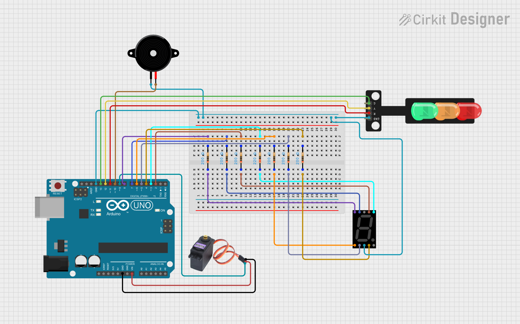
This circuit is a color sorting machine that uses an Arduino UNO microcontroller to control a seven-segment display, a traffic light, a piezo speaker, and a servo motor (MG996R). The Arduino UNO reads color values from a color sensor and sorts objects based on their color. The seven-segment display shows the color values, the traffic light indicates the status, and the piezo speaker provides audio feedback.
Component List
Arduino UNO
- Description: A microcontroller board based on the ATmega328P.
- Pins: UNUSED, IOREF, Reset, 3.3V, 5V, GND, Vin, A0, A1, A2, A3, A4, A5, SCL, SDA, AREF, D13, D12, D11, D10, D9, D8, D7, D6, D5, D4, D3, D2, D1, D0
Traffic Light
- Description: A traffic light module with three LEDs (Green, Yellow, Red) and a ground pin.
- Pins: Green, Yellow, Red, GND
Piezo Speaker
- Description: A piezoelectric speaker for generating sound.
- Pins: pin1, pin2
MG996R Servo Motor
- Description: A high-torque servo motor.
- Pins: GND, VCC, SIG
Seven Segment Display (Wokwi Compatible)
- Description: A seven-segment display for showing numerical values.
- Pins: G, F, COM.2, B, A, E, D, COM.1, C, DP
Resistors
- Description: Various resistors used for current limiting.
- Pins: pin1, pin2
- Properties:
- Resistance: 200 Ohms (5 instances)
- Resistance: 220 Ohms (1 instance)
Wiring Details
Arduino UNO
- D8: Connected to Resistor pin2 (200 Ohms) -> Seven Segment Display pin G
- D7: Connected to Resistor pin2 (200 Ohms) -> Seven Segment Display pin F
- D2: Connected to Resistor pin2 (200 Ohms) -> Seven Segment Display pin A
- D3: Connected to Resistor pin2 (220 Ohms) -> Seven Segment Display pin B
- D6: Connected to Resistor pin2 (200 Ohms) -> Seven Segment Display pin E
- D5: Connected to Resistor pin2 (200 Ohms) -> Seven Segment Display pin D
- D4: Connected to Resistor pin2 (200 Ohms) -> Seven Segment Display pin C
- GND: Connected to Piezo Speaker pin1, Seven Segment Display pin COM.1, Traffic Light GND, MG996R GND
- Vin: Connected to MG996R VCC
- D13: Connected to Traffic Light Green
- D12: Connected to Traffic Light Yellow
- D11: Connected to Traffic Light Red
- D10: Connected to Piezo Speaker pin2
- D9: Connected to MG996R SIG
Traffic Light
- Green: Connected to Arduino UNO D13
- Yellow: Connected to Arduino UNO D12
- Red: Connected to Arduino UNO D11
- GND: Connected to Arduino UNO GND
Piezo Speaker
- pin1: Connected to Arduino UNO GND
- pin2: Connected to Arduino UNO D10
MG996R Servo Motor
- GND: Connected to Arduino UNO GND
- VCC: Connected to Arduino UNO Vin
- SIG: Connected to Arduino UNO D9
Seven Segment Display (Wokwi Compatible)
- G: Connected to Resistor pin1 (200 Ohms) -> Arduino UNO D8
- F: Connected to Resistor pin1 (200 Ohms) -> Arduino UNO D7
- A: Connected to Resistor pin1 (200 Ohms) -> Arduino UNO D2
- B: Connected to Resistor pin1 (220 Ohms) -> Arduino UNO D3
- E: Connected to Resistor pin1 (200 Ohms) -> Arduino UNO D6
- D: Connected to Resistor pin1 (200 Ohms) -> Arduino UNO D5
- C: Connected to Resistor pin1 (200 Ohms) -> Arduino UNO D4
- COM.1: Connected to Arduino UNO GND
Resistors
- 200 Ohms: Connected between Seven Segment Display pins (G, F, A, E, D, C) and Arduino UNO pins (D8, D7, D2, D6, D5, D4)
- 220 Ohms: Connected between Seven Segment Display pin B and Arduino UNO pin D3
Documented Code
/*Color Sorting Machine by : Omar Wael Morsi*/
/*YouTube : Morsi Hamed  https://www.youtube.com/c/morsihamed */

#include <Servo.h>
#define S0 2
#define S1 3
#define S2 4
#define S3 5
#define sensorOut 6
Servo topServo;
Servo bottomServo;
int frequency = 0;
int color = 0;

void setup() {
  pinMode(S0, OUTPUT);
  pinMode(S1, OUTPUT);
  pinMode(S2, OUTPUT);
  pinMode(S3, OUTPUT);
  pinMode(sensorOut, INPUT);
  digitalWrite(S0, HIGH); //20% scalling
  digitalWrite(S1, LOW);
  topServo.attach(9);
  bottomServo.attach(10);
  Serial.begin(9600);
}

void loop() {
  topServo.write(83); //set top servo at the first hole to catch the candy
  delay(500);

  for(int i = 83; i >= 30; i--) { //move top servo with the candy to the color sensor position
    topServo.write(i);
    delay(2);
  }
  delay(500);

  color = readColor(); //read the value from color sensor and put the bottom servo in the right path
  delay(10);
  switch (color) {
    case 1:
    bottomServo.write(15);
    break;
    case 2:
    bottomServo.write(60);
    break;
    case 3:
    bottomServo.write(110);
    break;

    case 0:
    break;
  }
  delay(300);

  for(int i = 30; i >= 0; i--) { //move top servo with candy from the color sensor position to the second hole position
    topServo.write(i);
    delay(2);
  }
  delay(200);

  for(int i = 0; i <= 83; i++) { //return top servo to the first position to catch another candy
    topServo.write(i);
    delay(2);
  }
  color=0;
}

int readColor() { //color sensor function to read the color

  // Setting red
  digitalWrite(S2, LOW);
  digitalWrite(S3, LOW);
  frequency = pulseIn(sensorOut, LOW);
  int R = frequency;
  Serial.print("R= ");
  Serial.print(frequency);
  Serial.print("  ");
  delay(50);

  // Setting Green
  digitalWrite(S2, HIGH);
  digitalWrite(S3, HIGH);
  frequency = pulseIn(sensorOut, LOW);
  int G = frequency;
  Serial.print("G= ");
  Serial.print(frequency);
  Serial.print("  ");
  delay(50);

  // Setting Blue
  digitalWrite(S2, LOW);
  digitalWrite(S3, HIGH);
  frequency = pulseIn(sensorOut, LOW);
  int B = frequency;
  Serial.print("B= ");
  Serial.print(frequency);
  Serial.println("  ");
  delay(50);

  if(R<65 & R>50 & G>83 & G<95 & B>60 & B<70){
    color = 1; // Red
  }
  if(G<70 & G>55 & R<75 & R>65 &B<65 & B>54){
    color = 2; // Green
  }
  if (B<60 &B>40 & G>68 & G<85 & R>75 & R<95){
    color = 3; // Blue
  }
  return color;
}
/*i hope this was helpful for you please check tutorial video in my youtube channel*/
/*and if you have any question i will be happy answering it :)*/
/*Servo tutorial : https://youtu.be/FXCSVss93XU*/
/*Color Sensor tutorial : https://youtu.be/IqVtrWKNfCw*/
/* https://www.youtube.com/playlist?list=PLJRh_zZSG_PT0lJAzx0eTCyPwk_obpJjt */
This documentation provides a comprehensive overview of the circuit, including the components used, their wiring details, and the code running on the Arduino UNO.