ESP8266 NodeMCU Controlled Relay with ADS1115 and Piezo Buzzer Notification
Circuit Documentation
Summary
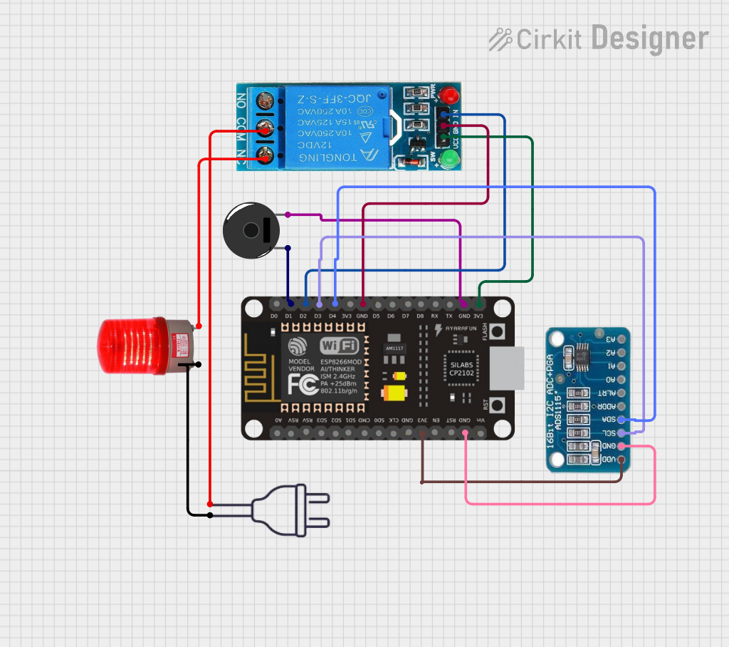
The circuit in question appears to be designed for interfacing an ESP8266 NodeMCU microcontroller with several peripheral devices, including an ADS1115 analog-to-digital converter (ADC), a 12V single-channel relay, a piezo buzzer, and a red light that operates at 220VAC. The ESP8266 NodeMCU is responsible for controlling the relay and the buzzer, as well as communicating with the ADC via I2C protocol. The relay is used to switch the red light on and off, and the power supply provides 220VAC to the relay and the light.
Component List
ESP8266 NodeMCU
- Microcontroller with WiFi capability.
- Pins: D0-D8, RX, TX, A0, RSV, SD3, SD2, SD1, CMD, SD0, CLK, EN, RST, VIN, 3V3, GND.
Red Light 220VAC
- An indicator light that operates at 220VAC.
- Pins: -, +.
ADS1115
- A high-precision ADC with I2C interface.
- Pins: VDD, GND, SCL, SDA, ADDR, ALRT, A0-A3.
Power 220V
- A power supply module that provides 220VAC.
- Pins: hot wire, neutral wire.
Piezo Buzzer
- An audible signaling device.
- Pins: pin 1, pin 2.
12V Single Channel Relay
- An electromechanical switch that can be controlled by the ESP8266 NodeMCU.
- Pins: NC, COM, NO, IN, GND, VCC.
Wiring Details
ESP8266 NodeMCU
- D1 connected to Piezo Buzzer pin 1.
- D2 connected to 12V Single Channel Relay IN.
- D3 connected to ADS1115 SCL.
- D4 connected to ADS1115 SDA.
- GND connected to 12V Single Channel Relay GND, Piezo Buzzer pin 2, and ADS1115 GND.
- 3V3 connected to 12V Single Channel Relay VCC and ADS1115 VDD.
Red Light 220VAC
- connected to 12V Single Channel Relay NC.
- connected to Power 220V neutral wire.
ADS1115
- SCL connected to ESP8266 NodeMCU D3.
- SDA connected to ESP8266 NodeMCU D4.
- VDD connected to ESP8266 NodeMCU 3V3.
- GND connected to ESP8266 NodeMCU GND.
Power 220V
- neutral wire connected to Red Light 220VAC +.
- hot wire connected to 12V Single Channel Relay COM.
Piezo Buzzer
- pin 1 connected to ESP8266 NodeMCU D1.
- pin 2 connected to ESP8266 NodeMCU GND.
12V Single Channel Relay
- IN connected to ESP8266 NodeMCU D2.
- GND connected to ESP8266 NodeMCU GND.
- VCC connected to ESP8266 NodeMCU 3V3.
- NC connected to Red Light 220VAC -.
- COM connected to Power 220V hot wire.
Documented Code
No code has been provided for the microcontroller. The expected code should handle the initialization and control of the I2C interface for communication with the ADS1115 ADC, as well as the digital outputs to control the relay and the buzzer. It should also include routines for reading the ADC values and possibly for WiFi communication, given the capabilities of the ESP8266 NodeMCU.