
ESP32-Based Smart Sensor System with GPS and GSM Integration
View and Edit Project In Cirkit Designer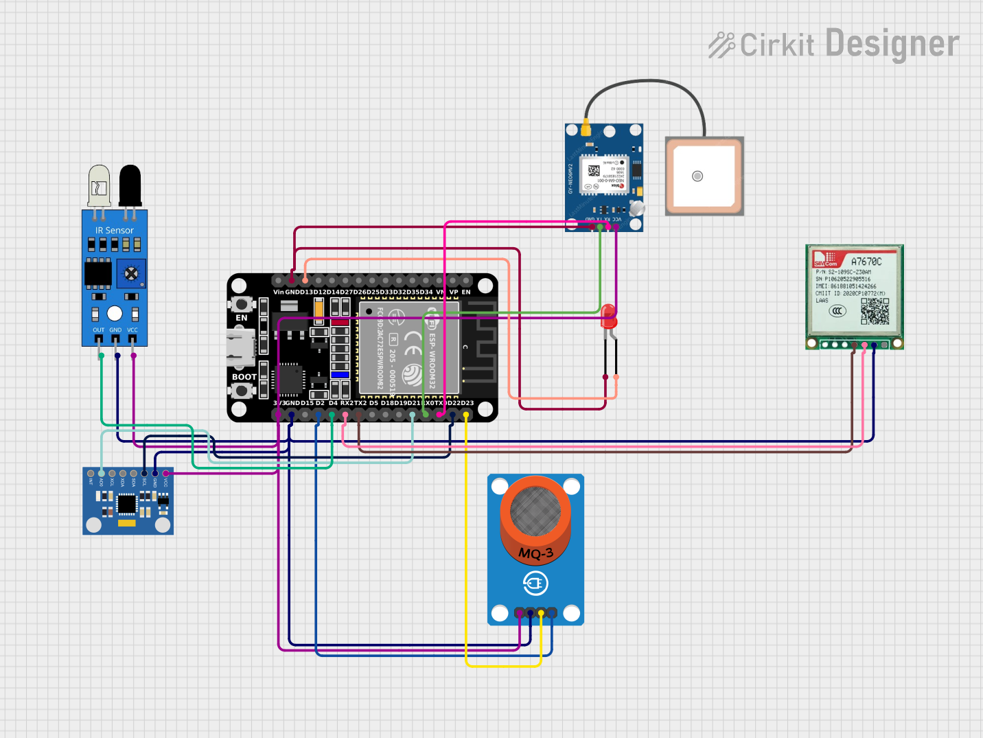
Circuit Documentation
Summary
This document provides a detailed overview of a circuit that integrates various sensors and modules with an ESP32 microcontroller. The circuit includes an MQ-3 alcohol sensor, an MPU6050 accelerometer and gyroscope, an IR sensor, a GPS module, a GSM module, and an LED. The ESP32 microcontroller is programmed to read data from these sensors, control the LED, and send data to a cloud server and via SMS.
Component List
ESP32 (30 pin)
- Description: A powerful microcontroller with built-in WiFi and Bluetooth capabilities.
- Pins: EN, VP, VN, D34, D35, D32, D33, D25, D26, D27, D14, D12, D13, GND, Vin, D23, D22, TX0, RX0, D21, D19, D18, D5, TX2, RX2, D4, D2, D15, 3V3
MQ-3 Breakout
- Description: An alcohol sensor used to detect the presence of alcohol in the air.
- Pins: VCC, GND, DO, AO
LED: Two Pin (red)
- Description: A simple red LED.
- Pins: cathode, anode
MPU6050 Accelerometer + Gyroscope (Wokwi Compatible)
- Description: A sensor module that provides accelerometer and gyroscope data.
- Pins: INT, AD0, XCL, XDA, SDA, SCL, GND, VCC
IR Sensor
- Description: An infrared sensor used to detect objects.
- Pins: out, gnd, vcc
Sim A7670c
- Description: A GSM module used for sending SMS.
- Pins: Vin, Gnd, Tx, Rx
GPS NEO 6M
- Description: A GPS module used for obtaining location data.
- Pins: VCC, RX, TX, GND
Wiring Details
ESP32 (30 pin)
- D13: Connected to the anode of the LED.
- GND: Connected to the cathode of the LED, GND of GPS NEO 6M, GND of MQ-3 Breakout, GND of IR sensor, GND of MPU6050, and GND of Sim A7670c.
- D23: Connected to DO of MQ-3 Breakout.
- D22: Connected to SCL of MPU6050.
- TX0: Connected to RX of GPS NEO 6M.
- RX0: Connected to TX of GPS NEO 6M.
- D21: Connected to AD0 of MPU6050.
- TX2: Connected to Rx of Sim A7670c.
- RX2: Connected to Tx of Sim A7670c.
- D4: Connected to out of IR sensor.
- D2: Connected to AO of MQ-3 Breakout.
- 3V3: Connected to VCC of MQ-3 Breakout, VCC of IR sensor, VCC of MPU6050, and VCC of GPS NEO 6M.
MQ-3 Breakout
- DO: Connected to D23 of ESP32.
- AO: Connected to D2 of ESP32.
- GND: Connected to GND of ESP32, GND of IR sensor, GND of MPU6050, and GND of Sim A7670c.
- VCC: Connected to 3V3 of ESP32.
LED: Two Pin (red)
- anode: Connected to D13 of ESP32.
- cathode: Connected to GND of ESP32 and GND of GPS NEO 6M.
MPU6050 Accelerometer + Gyroscope (Wokwi Compatible)
- SCL: Connected to D22 of ESP32.
- AD0: Connected to D21 of ESP32.
- GND: Connected to GND of ESP32, GND of MQ-3 Breakout, GND of IR sensor, and GND of Sim A7670c.
- VCC: Connected to 3V3 of ESP32.
IR Sensor
- out: Connected to D4 of ESP32.
- gnd: Connected to GND of ESP32, GND of MQ-3 Breakout, GND of MPU6050, and GND of Sim A7670c.
- vcc: Connected to 3V3 of ESP32.
Sim A7670c
- Rx: Connected to TX2 of ESP32.
- Tx: Connected to RX2 of ESP32.
- Gnd: Connected to GND of ESP32, GND of MQ-3 Breakout, GND of IR sensor, and GND of MPU6050.
- Vin: Not connected.
GPS NEO 6M
- RX: Connected to TX0 of ESP32.
- TX: Connected to RX0 of ESP32.
- GND: Connected to GND of ESP32 and GND of LED.
- VCC: Connected to 3V3 of ESP32.
Documented Code
ESP32 Code
#include <Wire.h>
#include <Adafruit_MPU6050.h>
#include <Adafruit_Sensor.h>
#include <WiFi.h>
#include <HTTPClient.h>
#include <SoftwareSerial.h>

// WiFi credentials
const char* ssid = "Your_SSID";
const char* password = "Your_PASSWORD";

// Cloud server details (optional if you want cloud integration)
const char* serverName = "https://your-cloud-server.com/api";

// GSM Module pins for A7670C
#define A7670C_RX 16  // ESP32 RX pin (for A7670C TX)
#define A7670C_TX 17  // ESP32 TX pin (for A7670C RX)

SoftwareSerial gsmSerial(A7670C_RX, A7670C_TX);  // Create a software serial for A7670C communication

// Sensors and pins
const int analogPin = 2;  // MQ-3 AO connected to ESP32 D2
const int digitalPin = 23; // MQ-3 DO connected to ESP32 D23
const int ledPin = 13; // Onboard LED
const int irPin = 4; // IR sensor output connected to ESP32 D4

Adafruit_MPU6050 mpu; // MPU6050 instance

// Phone number and message for SMS
const char *phoneNumber = "+1234567890"; // Replace with the recipient's phone number
String message = "";

void setup() {
  Serial.begin(115200);
  gsmSerial.begin(9600);  // Initialize GSM communication (A7670C baud rate)

  pinMode(digitalPin, INPUT);
  pinMode(ledPin, OUTPUT);
  pinMode(irPin, INPUT);

  // Initialize MPU6050
  if (!mpu.begin()) {
    Serial.println("Failed to find MPU6050 chip");
    while (1) delay(10);
  }
  Serial.println("MPU6050 initialized!");

  // Configure MPU6050
  mpu.setAccelerometerRange(MPU6050_RANGE_2_G); // ±2g
  mpu.setGyroRange(MPU6050_RANGE_250_DEG);     // ±250°/s
  mpu.setFilterBandwidth(MPU6050_BAND_21_HZ);  // 21 Hz filter

  // Connect to WiFi
  connectToWiFi();
}

void loop() {
  // Read sensor values
  int analogValue = analogRead(analogPin);
  int digitalValue = digitalRead(digitalPin);
  int irValue = digitalRead(irPin);

  // Print sensor values to serial
  Serial.print("Analog Value: ");
  Serial.println(analogValue);
  Serial.print("IR Sensor Value: ");
  Serial.println(irValue);

  // LED control based on digital pin
  digitalWrite(ledPin, digitalValue);

  // Fetch GPS data
  String gpsData = fetchGPSData();

  // If GPS data is valid, send to cloud and SMS
  if (!gpsData.isEmpty()) {
    sendToCloud(gpsData, analogValue, irValue);
    message = "GPS: " + gpsData + " | Alcohol Level: " + String(analogValue) + " | IR Value: " + String(irValue);
    sendSMS(phoneNumber, message);  // Send SMS with sensor data
  }

  delay(1000); // Delay 1 second
}

void connectToWiFi() {
  Serial.print("Connecting to WiFi...");
  WiFi.begin(ssid, password);
  while (WiFi.status() != WL_CONNECTED) {
    delay(1000);
    Serial.print(".");
  }
  Serial.println("\nWiFi connected!");
  Serial.print("IP Address: ");
  Serial.println(WiFi.localIP());
}

String fetchGPSData() {
  // Simulated GPS data (replace with actual GPS fetch logic)
  String latitude = "17.385044"; // Replace with parsed