
Arduino-Controlled Security System with Wi-Fi Connectivity and Automated Lighting
View and Edit Project In Cirkit Designer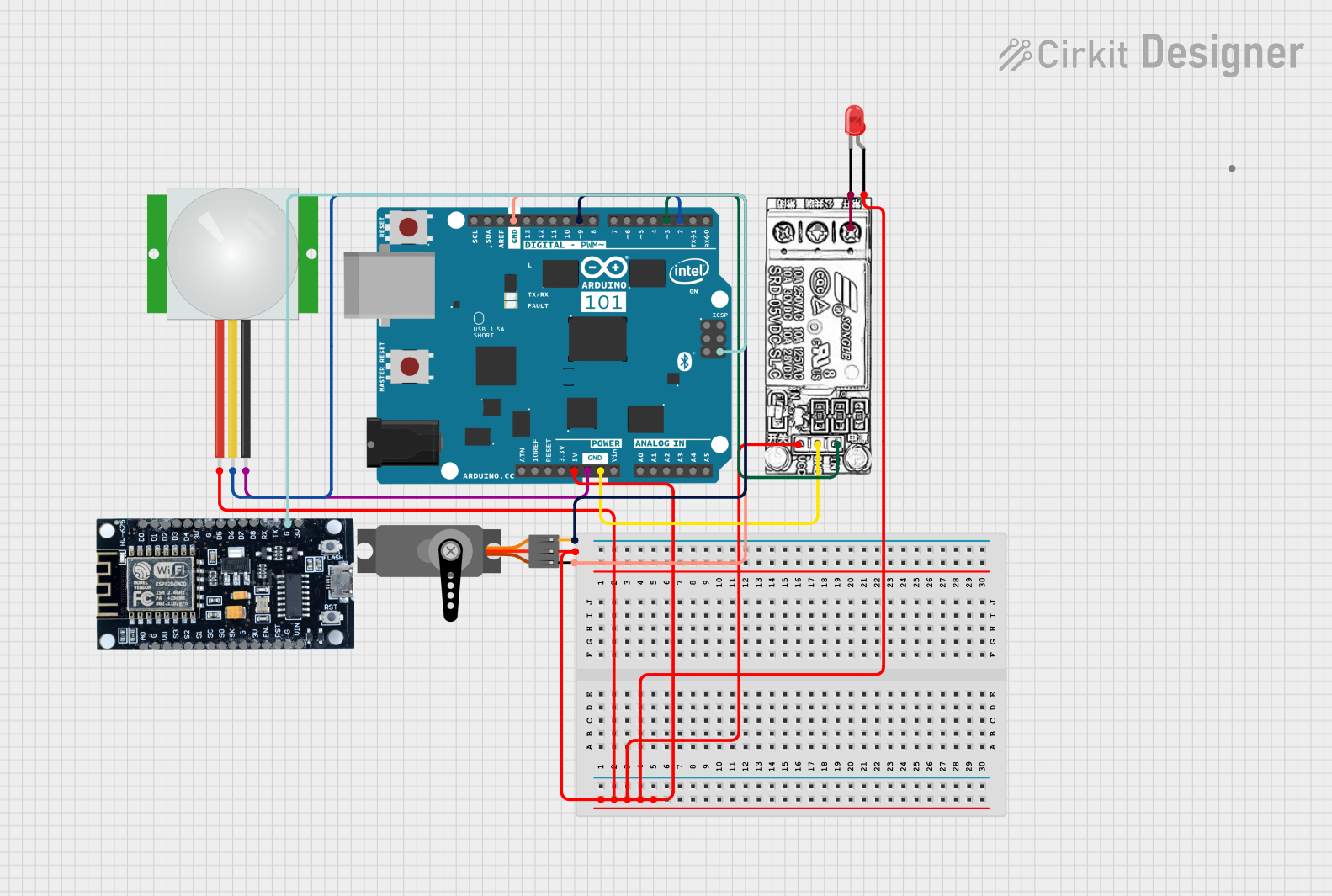
Circuit Documentation
Summary of the Circuit
This circuit is designed to control a servo and a relay module based on the input from a PIR (Passive Infrared) sensor. The Arduino 101 microcontroller serves as the central processing unit, reading the PIR sensor's output to detect motion and then activating the relay and servo accordingly. Additionally, the circuit includes an ESP8266 module for potential WiFi capabilities, allowing for remote commands to be sent to the Arduino. An LED is also connected to the relay module to indicate the relay's state.
Component List
LED: Two Pin (red)
- Description: A red LED used to indicate the status of the relay.
- Pins: cathode, anode
Servo
- Description: A servo motor used to perform physical actions, such as opening a door or moving a lever.
- Pins: GND, VCC, PWM
RELAY MODULE
- Description: An electromechanical switch used to control a high-power circuit with a low-power signal.
- Pins: NC, COM, INPUT, GND, VCC
Arduino 101
- Description: A microcontroller board based on the Intel Curie Module, used as the main controller in this circuit.
- Pins: A5/SCL, A4/SDA, AREF, GND, D13/SCK, D12/MISO, D11 PWM/MOSI, D10 PWM/SS, D9 PWM, D8, D7, D6 PWM, D5 PWM, D4, D3 PWM, D2, D1/TX, D0/RX, AIN, ioref, RESET, 3V3, 5V, VIN, A0, A1, A2, A3, ICSP MISO, ICSP SCK, ICSP MOSI
PIR sensor
- Description: A sensor that detects motion by measuring changes in the infrared levels emitted by surrounding objects.
- Pins: VDD, SIG, GND
ESP8266
- Description: A low-cost Wi-Fi microchip with full TCP/IP stack and microcontroller capability.
- Pins: 3V, G, D8, D7, D6, D5, D4, D3, D2, D1, D0, A0, S3, S2, S1, SC, S0, SK, EN, VIN, RST, VU
Wiring Details
LED: Two Pin (red)
- Anode: Connected to the VCC of the relay module.
- Cathode: Connected to the NC (Normally Closed) pin of the relay module.
Servo
- GND: Connected to the GND of the Arduino 101.
- VCC: Connected to the 5V of the Arduino 101.
- PWM: Connected to the D9 PWM pin of the Arduino 101.
RELAY MODULE
- NC: Connected to the cathode of the LED.
- COM: Not connected in this circuit.
- INPUT: Connected to the D3 PWM pin of the Arduino 101.
- GND: Connected to the GND of the Arduino 101.
- VCC: Connected to the 5V of the Arduino 101.
Arduino 101
- 5V: Connected to the VCC of the PIR sensor, relay module, LED, and servo.
- GND: Connected to the GND of the PIR sensor, relay module, servo, and ESP8266.
- D9 PWM: Connected to the PWM pin of the servo.
- D3 PWM: Connected to the INPUT pin of the relay module.
- D2: Connected to the SIG pin of the PIR sensor.
PIR sensor
- VDD: Connected to the 5V of the Arduino 101.
- SIG: Connected to the D2 pin of the Arduino 101.
- GND: Connected to the GND of the Arduino 101.
ESP8266
- G: Connected to the GND of the Arduino 101.
- Other Pins: Not connected in this circuit.
Documented Code
Arduino 101 Code
#include <Servo.h>

Servo myServo;
const int pirPin = 2;  // Pin for PIR sensor
const int relayPin = 3; // Pin for relay
int pirState = LOW;     // Initial state for PIR
int val = 0;            // Variable to store the sensor value

void setup() {
  myServo.attach(9);          // Connect servo to pin 9
  pinMode(pirPin, INPUT);     // Set PIR pin as input
  pinMode(relayPin, OUTPUT);  // Set relay pin as output
  Serial.begin(115200);       // Start serial communication at 115200 baud rate
}

void loop() {
  val = digitalRead(pirPin); // Read PIR status
  if (val == HIGH) {         // If motion detected
    if (pirState == LOW) {
      Serial.println("Motion detected!"); // Notify via Serial
      digitalWrite(relayPin, HIGH); // Turn on the light
      myServo.write(90);             // Open the door (adjust angle as needed)
      delay(2000);                   // Wait for a few seconds
      myServo.write(0);              // Close the door
      pirState = HIGH;               // Set PIR status
    }
  } else {
    digitalWrite(relayPin, LOW);    // Turn off the light if no motion is detected
    pirState = LOW;                  // Reset PIR status
  }

  // Check for commands from ESP8266 via Serial
  if (Serial.available()) {
    String command = Serial.readStringUntil('\n'); // Read command from ESP8266
    if (command == "ON") {
      Serial.println("Light turned on");
      digitalWrite(relayPin, HIGH); // Turn on the light
    } else if (command == "OFF") {
      Serial.println("Light turned off");
      digitalWrite(relayPin, LOW);  // Turn off the light
    }
  }
}
ESP8266 Code
#include <ESP8266WiFi.h>

const char* ssid = "Your_SSID"; // Replace with your Wi-Fi SSID
const char* password = "Your_PASSWORD"; // Replace with your Wi-Fi password

void setup() {
  Serial.begin(115200); // Start serial communication
  WiFi.begin(ssid, password); // Connect to Wi-Fi
  while (WiFi.status() != WL_CONNECTED) {
    delay(1000);
    Serial.println("Connecting to WiFi...");
  }
  Serial.println("Connected to WiFi");
}

void loop() {
  // Code to control devices or take input from applications
  // For example, sending commands to Arduino
  Serial.println("ON"); // Send command to turn on the light
  delay(5000); // Wait for 5 seconds
  Serial.println("OFF"); // Send command to turn off the light
  delay(5000); // Wait for 5 seconds
}
This concludes the documentation for the given circuit design and embedded code.