
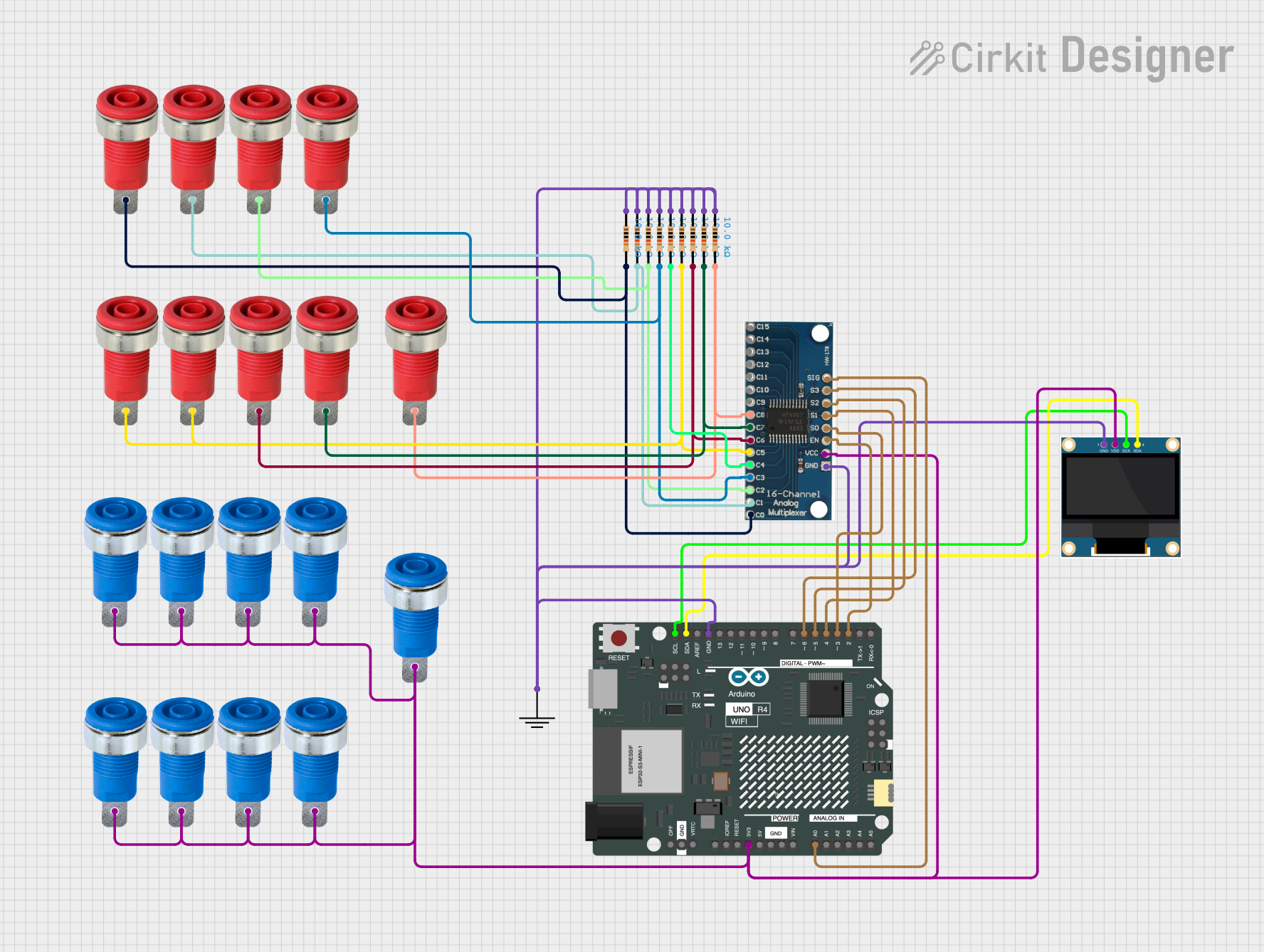
Circuit Documentation
Summary
This circuit is designed to test the continuity of connections using an Arduino UNO R4 WiFi microcontroller, a 0.96" OLED display, a 16-channel analog multiplexer, and several resistors and banana sockets. The Arduino controls the multiplexer to select different channels and reads the continuity status, displaying the results on the OLED screen.
Component List
Arduino UNO R4 WiFi
- Description: Microcontroller board based on the ATmega328P.
- Pins: OFF, GND, VRTC, IIC0_SCL, IIC0_SDA, 3V3, GPIO 41, GPIO 0, GPIO 42, GPIO 43, GPIO 44, BOOT, IOREF, RESET, 5V, VIN, A0, A1, A2, A3, A4, A5, RSPCKA, CIPO, COPI, D0/RX, D1/TX, D2, D3, D4, D5, D6, D7, D8, D9, D10, D11, D12, D13, AREF, SDA, SCL
0.96" OLED
- Description: Small OLED display module.
- Pins: GND, VDD, SCK, SDA
GND
- Description: Ground connection.
- Pins: GND
16-channel analog multiplexer
- Description: Multiplexer for selecting one of 16 analog inputs.
- Pins: GND, VCC, EN, S0, S1, S2, S3, SIG, C0, C1, C2, C3, C4, C5, C6, C7, C8, C9, C10, C11, C12, C13, C14, C15
Resistor (10k Ohms)
- Description: Resistor with a resistance of 10k Ohms.
- Pins: pin1, pin2
Blue Panel Mount 4mm Banana Socket
- Description: Blue banana socket for panel mounting.
- Pins: Blue_Pin
Red Panel Mount 4mm Banana Socket
- Description: Red banana socket for panel mounting.
- Pins: Red_Pin
Wiring Details
Arduino UNO R4 WiFi
3V3 connected to:
- VDD of 0.96" OLED
- VCC of 16-channel analog multiplexer
- Blue_Pin of multiple Blue Panel Mount 4mm Banana Sockets
GND connected to:
- GND of 0.96" OLED
- GND of 16-channel analog multiplexer
- GND of GND component
- pin1 of multiple 10k Ohm Resistors
A0 connected to:
- SIG of 16-channel analog multiplexer
D2 connected to:
- EN of 16-channel analog multiplexer
D3 connected to:
- S0 of 16-channel analog multiplexer
D4 connected to:
- S1 of 16-channel analog multiplexer
D5 connected to:
- S2 of 16-channel analog multiplexer
D6 connected to:
- S3 of 16-channel analog multiplexer
SDA connected to:
- SDA of 0.96" OLED
SCL connected to:
- SCK of 0.96" OLED
0.96" OLED
VDD connected to:
- 3V3 of Arduino UNO R4 WiFi
GND connected to:
- GND of Arduino UNO R4 WiFi
SCK connected to:
- SCL of Arduino UNO R4 WiFi
SDA connected to:
- SDA of Arduino UNO R4 WiFi
16-channel analog multiplexer
VCC connected to:
- 3V3 of Arduino UNO R4 WiFi
GND connected to:
- GND of Arduino UNO R4 WiFi
EN connected to:
- D2 of Arduino UNO R4 WiFi
S0 connected to:
- D3 of Arduino UNO R4 WiFi
S1 connected to:
- D4 of Arduino UNO R4 WiFi
S2 connected to:
- D5 of Arduino UNO R4 WiFi
S3 connected to:
- D6 of Arduino UNO R4 WiFi
SIG connected to:
- A0 of Arduino UNO R4 WiFi
C0 connected to:
- pin2 of a 10k Ohm Resistor
- Red_Pin of a Red Panel Mount 4mm Banana Socket
C1 connected to:
- pin2 of a 10k Ohm Resistor
- Red_Pin of a Red Panel Mount 4mm Banana Socket
C2 connected to:
- pin2 of a 10k Ohm Resistor
- Red_Pin of a Red Panel Mount 4mm Banana Socket
C3 connected to:
- pin2 of a 10k Ohm Resistor
- Red_Pin of a Red Panel Mount 4mm Banana Socket
C4 connected to:
- pin2 of a 10k Ohm Resistor
C5 connected to:
- pin2 of a 10k Ohm Resistor
- Red_Pin of multiple Red Panel Mount 4mm Banana Sockets
C6 connected to:
- pin2 of a 10k Ohm Resistor
- Red_Pin of a Red Panel Mount 4mm Banana Socket
C7 connected to:
- pin2 of a 10k Ohm Resistor
- Red_Pin of a Red Panel Mount 4mm Banana Socket
C8 connected to:
- pin2 of a 10k Ohm Resistor
- Red_Pin of a Red Panel Mount 4mm Banana Socket
Resistors (10k Ohms)
pin1 connected to:
- GND of Arduino UNO R4 WiFi
pin2 connected to:
- C0, C1, C2, C3, C4, C5, C6, C7, C8 of 16-channel analog multiplexer
- Red_Pin of multiple Red Panel Mount 4mm Banana Sockets
Blue Panel Mount 4mm Banana Socket
- Blue_Pin connected to:
- 3V3 of Arduino UNO R4 WiFi
Red Panel Mount 4mm Banana Socket
- Red_Pin connected to:
- pin2 of multiple 10k Ohm Resistors
- C0, C1, C2, C3, C5, C6, C7, C8 of 16-channel analog multiplexer
Code Documentation
#include <Wire.h>
#include <Adafruit_GFX.h>
#include <Adafruit_SSD1306.h>

#define SCREEN_WIDTH 128
#define SCREEN_HEIGHT 64
#define OLED_RESET    -1
Adafruit_SSD1306 display(SCREEN_WIDTH, SCREEN_HEIGHT, &Wire, OLED_RESET);

const int buttonPin = 7;
const int muxSIG = A0;
const int muxEN = 2;
const int muxS0 = 3;
const int muxS1 = 4;
const int muxS2 = 5;
const int muxS3 = 6;

bool testing = true; // Startet direkt mit der Messung

void setup() {
  Serial.begin(9600); // Initialisiere die serielle Kommunikation
  pinMode(buttonPin, INPUT_PULLUP);
  pinMode(muxEN, OUTPUT);
  pinMode(muxS0, OUTPUT);
  pinMode(muxS1, OUTPUT);
  pinMode(muxS2, OUTPUT);
  pinMode(muxS3, OUTPUT);
  digitalWrite(muxEN, LOW);
  display.begin(SSD1306_SWITCHCAPVCC, 0x3C);
  display.display();
  delay(2000);
  display.clearDisplay();
  display.setTextSize(1);
  display.setTextColor(SSD1306_WHITE);
  display.setCursor(0, 0);
  display.print("Kabeltester");
  display.display();
}

void loop() {
  if (digitalRead(buttonPin) == LOW) {
    delay(50);
    if (digitalRead(buttonPin) == LOW) {
      testing = true; // Setzt die Messung zurück
      while (digitalRead(buttonPin) == LOW);
    }
  }
  if (testing) {
    display.clearDisplay();
    display.setCursor(0, 0);
    display.print("Teste...");
    display.setCursor(0, 10);
    bool allOK = true;

    // Teste Kontinuität zur Masse für jeden Kanal
    for (int i = 0; i < 5; i++) {
      setMuxChannel(i);
      delay