
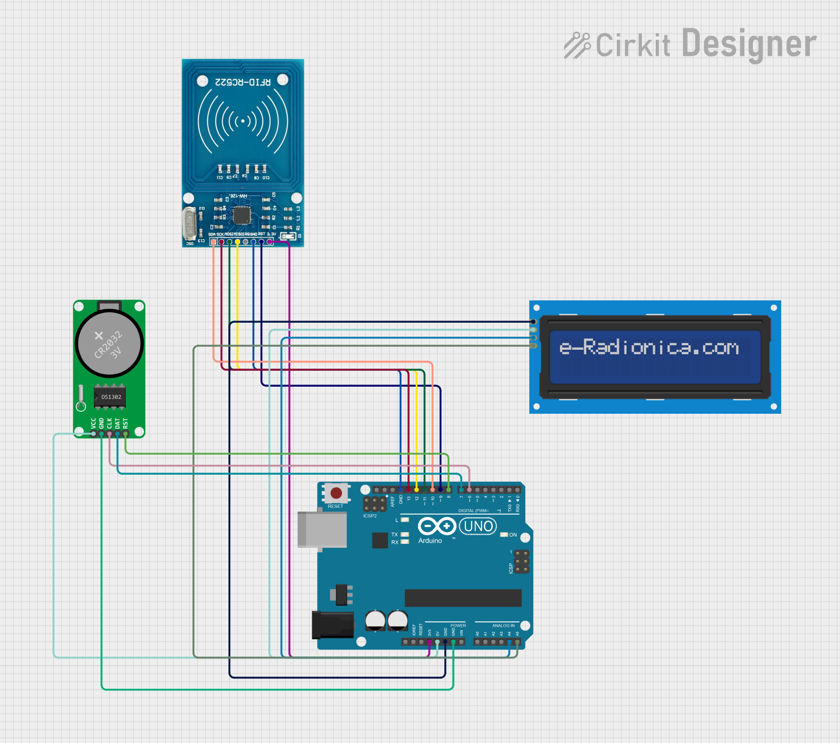
Circuit Documentation
Summary
This circuit is an attendance system that utilizes an Arduino UNO microcontroller to interface with an RFID reader (RFID-RC522), an LCD screen (16x2 I2C), and a Real-Time Clock (RTC-DS1302). The system reads RFID tags, displays information on the LCD, and keeps track of time using the RTC module.
Component List
Arduino UNO
- Description: A microcontroller board based on the ATmega328P.
- Pins: UNUSED, IOREF, Reset, 3.3V, 5V, GND, Vin, A0, A1, A2, A3, A4, A5, SCL, SDA, AREF, D13, D12, D11, D10, D9, D8, D7, D6, D5, D4, D3, D2, D1, D0
RFID-RC522
- Description: A low-cost RFID reader module.
- Pins: VCC (3.3V), RST, GND, IRQ, MISO, MOSI, SCK, SDA
LCD screen 16x2 I2C
- Description: A 16x2 character LCD display with I2C interface.
- Pins: SCL, SDA, VCC, GND
RTC-DS1302
- Description: A Real-Time Clock module.
- Pins: Vcc, GND, CLK, DAT, RST
Wiring Details
Arduino UNO
- 3.3V connected to RFID-RC522 VCC (3.3V)
- 5V connected to LCD screen 16x2 I2C VCC and RTC-DS1302 Vcc
- GND connected to LCD screen 16x2 I2C GND, RTC-DS1302 GND, and RFID-RC522 GND
- A4 connected to LCD screen 16x2 I2C SDA
- A5 connected to LCD screen 16x2 I2C SCL
- D13 connected to RFID-RC522 SCK
- D12 connected to RFID-RC522 MISO
- D11 connected to RFID-RC522 MOSI
- D10 connected to RFID-RC522 SDA
- D9 connected to RFID-RC522 RST
- D8 connected to RTC-DS1302 RST
- D7 connected to RTC-DS1302 DAT
- D6 connected to RTC-DS1302 CLK
RFID-RC522
- VCC (3.3V) connected to Arduino UNO 3.3V
- RST connected to Arduino UNO D9
- GND connected to Arduino UNO GND
- SCK connected to Arduino UNO D13
- MISO connected to Arduino UNO D12
- MOSI connected to Arduino UNO D11
- SDA connected to Arduino UNO D10
LCD screen 16x2 I2C
- SCL connected to Arduino UNO A5
- SDA connected to Arduino UNO A4
- VCC connected to Arduino UNO 5V
- GND connected to Arduino UNO GND
RTC-DS1302
- Vcc connected to Arduino UNO 5V
- GND connected to Arduino UNO GND
- CLK connected to Arduino UNO D6
- DAT connected to Arduino UNO D7
- RST connected to Arduino UNO D8
Code Documentation
#include <SPI.h>
#include <MFRC522.h>
#include <LiquidCrystal_I2C.h>
#include <ThreeWire.h>
#include <RtcDS1302.h>
#include <Wire.h>

// RFID pins
#define SS_PIN 10
#define RST_PIN 9
#define BUZZER_PIN 8
#define GREEN_LED 7
#define RED_LED 6

// RTC Pins
const int RTC_RST_PIN   = 8;  // Chip Enable
const int RTC_IO_PIN    = 7;  // Input/Output
const int RTC_SCLK_PIN  = 6;  // Serial Clock

// LCD Configuration
#define LCD_COLUMNS 16
#define SCROLL_DELAY 300  // Delay between each scroll step (ms)
#define PAUSE_TIME 2000   // Time to pause at the end of scroll (ms)

// Initialize objects
MFRC522 rfid(SS_PIN, RST_PIN);
LiquidCrystal_I2C lcd(0x27, 16, 2);
ThreeWire myWire(RTC_IO_PIN, RTC_SCLK_PIN, RTC_RST_PIN);
RtcDS1302<ThreeWire> Rtc(myWire);

// Is Eastern Daylight Savings Time?
bool isEDT = false;

// Scrolling text variables
String topMessage = "ATTENDANCE SYSTEM";
int scrollPosition = 0;
unsigned long lastScrollTime = 0;

// Known cards database
struct Card {
  byte uid[4];
  char name[20];
  bool isRegistered;
  bool isPresent;
  unsigned long lastScanTime;
};

const int MAX_CARDS = 25;
Card cards[MAX_CARDS] = {
  {{0xDA, 0x3D, 0xBA, 0x12}, "MUHAMMAD IRFAN", true, false, 0},
  {{0x33, 0x85, 0x47, 0x3E}, "PUAN WADA", true, false, 0},
  {{0x38, 0x55, 0x56, 0x66}, "SIR SHAFIQ", true, false, 0},
  {{0x6F, 0x7F, 0x9A, 0xBA}, "SARVESSH REDDIIY", true, false, 0},
  {{0x8F, 0x20, 0xB4, 0x4A}, "CHONG JING XIAN", true, false, 0},
  {{0x0F, 0xE4, 0xCF, 0xC9}, "VIKNESKUMARAN", true, false, 0},
  {{0x2F, 0xEC, 0x24, 0xCA}, "EIRFAN FARHAN", true, false, 0},
  {{0xAF, 0x1F, 0x26, 0x31}, "MUHAMMAD AKMAL", true, false, 0},
  {{0x55, 0x30, 0x73, 0xC9}, "SIR AKBAR", true, false, 0},
  {{0xB7, 0x7A, 0x51, 0x34}, "HASREET SINGH", true, false, 0},
  {{0x18, 0xC6, 0xD3, 0x7D}, "SHAHRIL IMAN", true, false, 0},
  {{0xAF, 0x59, 0x74, 0x49}, "HAKIMI IMRAN", true, false, 0},
  // Add more cards here
};

// Variables for timing
unsigned long startMillis;
const unsigned long SCAN_DELAY = 3000;

void setup() {
  Serial.begin(9600);

  // Initialize RFID
  SPI.begin();
  rfid.PCD_Init();

  // Initialize LCD
  lcd.init();
  lcd.backlight();

  // Initialize RTC
  Rtc.Begin();
  runRtcChecks();

  // Set RTC to compile time (do this only once)
  const char* nowDate = __DATE__;
  const char* nowTime = __TIME__;
  RtcDateTime compiled = RtcDateTime(nowDate, nowTime);
  Rtc.SetDateTime(compiled);

  // Set up pins
  pinMode(GREEN_LED, OUTPUT);
  pinMode(RED_LED, OUTPUT);
  pinMode(BUZZER_PIN, OUTPUT);

  startMillis = millis();

  // Serial output setup
  Serial.println("READY");
  Serial.println("CLEARDATA");
  Serial.println("CARD ID,NAME,STATUS,IN/OUT,TIME,DATE");

  // Determine Daylight Saving Time
  isEDT = isDaylightSavingTime(compiled);
}

void loop() {
  RtcDateTime now = Rtc.GetDateTime();

  if (!now.IsValid()) {
    lcd.clear();
    lcd.setCursor(0, 0);
    lcd.print("RTC Error!");
    return;
  }

  // Handle Daylight Saving Time adjustments
  adjustDaylightSavings(now);

  // Handle scroll display when no card is present
  if (!rfid.PICC_IsNewCardPresent()) {
    scrollText();
    displayCurrentDateTime(now);
    return;
  }

  if (!rfid