
Circuit Documentation
Summary of the Circuit
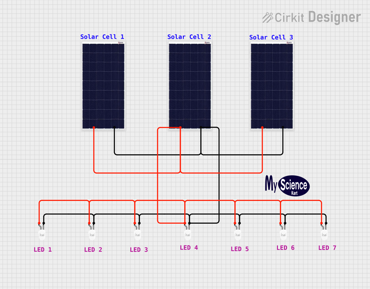
The circuit described by the provided inputs consists of a simple solar-powered LED array. There are three solar cells connected in parallel, each providing power to a parallel array of LEDs. The positive terminals of the solar cells are connected to the anodes of the LEDs, while the negative terminals are connected to the cathodes of the LEDs. This configuration allows the solar cells to power the LEDs when sufficient light is available to generate electricity.
Component List
Solar Cells
- Component Name: Solar Cell
- Description: A device that converts light into electrical energy.
- Purpose: To provide power to the LEDs in the circuit.
LEDs
- Component Name: LED: Two Pin (white)
- Description: A light-emitting diode that produces white light.
- Purpose: To emit light when powered by the solar cells.
Comments
- Component Name: Comment
- Description: Textual annotations for the circuit diagram.
- Purpose: To provide additional information or notes about the circuit.
Logo
- Component Name: Logo
- Description: A graphical representation or branding.
- Purpose: To visually represent a company or product associated with the circuit.
Wiring Details
Solar Cells
- Solar Cell
- Positive: Connected to the anodes of all LEDs.
- Negative: Connected to the cathodes of all LEDs.
LEDs
- LED: Two Pin (white)
- Anode: Connected to the positive terminal of the solar cells.
- Cathode: Connected to the negative terminal of the solar cells.
Documented Code
No microcontroller code has been provided for this circuit. The circuit operates purely on the electrical connections between the solar cells and the LEDs without the need for any embedded control logic.
This documentation provides an overview of the circuit's components, their purpose, and how they are wired together. Since there is no embedded code, the circuit's functionality is solely determined by the hardware configuration.