
Battery-Powered ESP32 CAM with FTDI Programmer for Wireless Applications
View and Edit Project In Cirkit Designer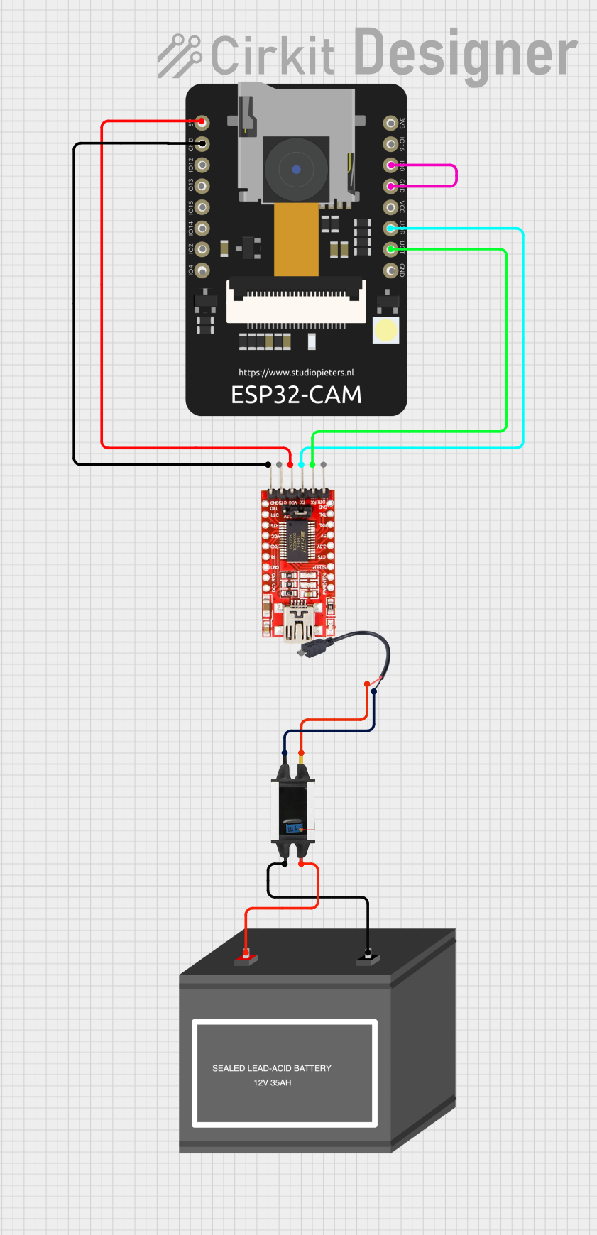
Circuit Documentation
Summary
This document provides a detailed overview of a circuit that includes an ESP32 CAM module, an FTDI Programmer, a Stepdown 18V to 5V converter, a Micro USB to Cable (2 Pin), and a 12V Battery (mini). The circuit is designed to power the ESP32 CAM module and facilitate communication with a computer via the FTDI Programmer. The Stepdown converter is used to step down the voltage from the 12V battery to 5V, which is then supplied to the ESP32 CAM and FTDI Programmer.
Component List
ESP32 CAM
- Description: A microcontroller with integrated Wi-Fi and Bluetooth, designed for camera applications.
- Pins: 5V, GND, GPIO12, GPIO13, GPIO15, GPIO14, GPIO2, GPIO4, 3.3V, GPIO16, GPIO0, 3.3V / 5V / P_OUT, GPIO3 / RX, GPIO1 / TX
FTDI Programmer
- Description: A USB-to-serial converter used to program and communicate with microcontrollers.
- Pins: DTR, RX, TX, VCC, CTS, GND
Stepdown 18V to 5V
- Description: A voltage converter that steps down 18V to 5V.
- Pins: VIN, GND IN, GND OUT, VOUT
Micro USB to Cable (2 Pin)
- Description: A micro USB connector with two output pins.
- Pins: Micro USB, +, -
12V Battery (mini)
- Description: A small 12V battery used to power the circuit.
- Pins: -, +
Wiring Details
ESP32 CAM
- 5V is connected to VCC of the FTDI Programmer.
- GND is connected to GND of the FTDI Programmer.
- GPIO0 is connected to GND of the ESP32 CAM.
- GPIO3 / RX is connected to TX of the FTDI Programmer.
- GPIO1 / TX is connected to RX of the FTDI Programmer.
FTDI Programmer
- VCC is connected to 5V of the ESP32 CAM.
- GND is connected to GND of the ESP32 CAM.
- TX is connected to GPIO3 / RX of the ESP32 CAM.
- RX is connected to GPIO1 / TX of the ESP32 CAM.
Stepdown 18V to 5V
- VIN is connected to + of the 12V Battery (mini).
- GND IN is connected to - of the 12V Battery (mini).
- GND OUT is connected to - of the Micro USB to Cable (2 Pin).
- VOUT is connected to + of the Micro USB to Cable (2 Pin).
Micro USB to Cable (2 Pin)
- - is connected to GND OUT of the Stepdown 18V to 5V.
- + is connected to VOUT of the Stepdown 18V to 5V.
12V Battery (mini)
- + is connected to VIN of the Stepdown 18V to 5V.
- - is connected to GND IN of the Stepdown 18V to 5V.
Code
There is no code provided for the microcontrollers in this circuit.
This document provides a comprehensive overview of the circuit, including a summary, component list, wiring details, and code documentation. The wiring details ensure that each component is correctly connected to achieve the desired functionality.