
Arduino Nano-Based Heart Rate and Oxygen Monitor with OLED Display
View and Edit Project In Cirkit Designer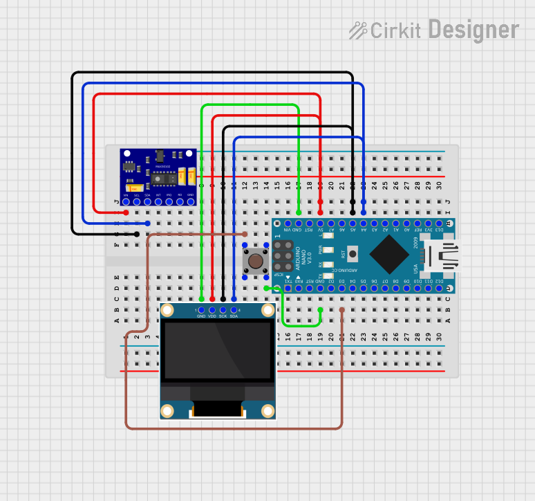
Circuit Documentation
Summary
This circuit is designed to measure heart rate and blood oxygen levels using a MAX30102 sensor and display the results on a 0.96" OLED screen. The circuit also includes a pushbutton for user interaction and is controlled by an Arduino Nano microcontroller.
Component List
Arduino Nano
- Description: A small, complete, and breadboard-friendly board based on the ATmega328P.
- Pins: D1/TX, D0/RX, RESET, GND, D2, D3, D4, D5, D6, D7, D8, D9, D10, D11/MOSI, D12/MISO, VIN, 5V, A7, A6, A5, A4, A3, A2, A1, A0, AREF, 3V3, D13/SCK
0.96" OLED
- Description: A small OLED display module for displaying text and graphics.
- Pins: GND, VDD, SCK, SDA
Pushbutton
- Description: A simple pushbutton for user input.
- Pins: Pin 3 (out), Pin 4 (out), Pin 1 (in), Pin 2 (in)
MAX30102 Heart Rate and Oxygen Sensor
- Description: A sensor module for measuring heart rate and blood oxygen levels.
- Pins: VIN, SCL, SDA, INT, IRQ, RD, GND
Wiring Details
Arduino Nano
5V connected to:
- 0.96" OLED (VDD)
- MAX30102 Heart Rate and Oxygen Sensor (VIN)
A5 connected to:
- 0.96" OLED (SCK)
- MAX30102 Heart Rate and Oxygen Sensor (SCL)
A4 connected to:
- 0.96" OLED (SDA)
- MAX30102 Heart Rate and Oxygen Sensor (SDA)
GND connected to:
- 0.96" OLED (GND)
- Pushbutton (Pin 4 (out))
D3 connected to:
- Pushbutton (Pin 1 (in))
0.96" OLED
VDD connected to:
- Arduino Nano (5V)
- MAX30102 Heart Rate and Oxygen Sensor (VIN)
SCK connected to:
- Arduino Nano (A5)
- MAX30102 Heart Rate and Oxygen Sensor (SCL)
SDA connected to:
- Arduino Nano (A4)
- MAX30102 Heart Rate and Oxygen Sensor (SDA)
GND connected to:
- Arduino Nano (GND)
Pushbutton
Pin 1 (in) connected to:
- Arduino Nano (D3)
Pin 4 (out) connected to:
- Arduino Nano (GND)
MAX30102 Heart Rate and Oxygen Sensor
VIN connected to:
- Arduino Nano (5V)
- 0.96" OLED (VDD)
SCL connected to:
- Arduino Nano (A5)
- 0.96" OLED (SCK)
SDA connected to:
- Arduino Nano (A4)
- 0.96" OLED (SDA)
GND connected to:
- Arduino Nano (GND)
Code Documentation
#include <Adafruit_SSD1306.h>
#include "MAX30102.h"
#include <Pulse.h>
#include <avr/pgmspace.h>
#include <EEPROM.h>
#include <avr/sleep.h>

#ifndef cbi
#define cbi(sfr, bit) (_SFR_BYTE(sfr) &= ~_BV(bit))
#endif
#ifndef sbi
#define sbi(sfr, bit) (_SFR_BYTE(sfr) |= _BV(bit))
#endif

SSD1306 oled;
MAX30102 sensor;
Pulse pulseIR;
Pulse pulseRed;
MAFilter bpm;

#define LED LED_BUILTIN
#define BUTTON 3
#define OPTIONS 7

static const uint8_t heart_bits[] PROGMEM = { 0x00, 0x00, 0x38, 0x38, 0x7c, 0x7c, 0xfe, 0xfe, 0xfe, 0xff,
                                        0xfe, 0xff, 0xfc, 0x7f, 0xf8, 0x3f, 0xf0, 0x1f, 0xe0, 0x0f,
                                        0xc0, 0x07, 0x80, 0x03, 0x00, 0x01, 0x00, 0x00, 0x00, 0x00,
                                        0x00, 0x00 };

//spo2_table is approximated as  -45.060*ratioAverage* ratioAverage + 30.354 *ratioAverage + 94.845 ;
const uint8_t spo2_table[184] PROGMEM =
        { 95, 95, 95, 96, 96, 96, 97, 97, 97, 97, 97, 98, 98, 98, 98, 98, 99, 99, 99, 99,
          99, 99, 99, 99, 100, 100, 100, 100, 100, 100, 100, 100, 100, 100, 100, 100, 100, 100, 100, 100,
          100, 100, 100, 100, 99, 99, 99, 99, 99, 99, 99, 99, 98, 98, 98, 98, 98, 98, 97, 97,
          97, 97, 96, 96, 96, 96, 95, 95, 95, 94, 94, 94, 93, 93, 93, 92, 92, 92, 91, 91,
          90, 90, 89, 89, 89, 88, 88, 87, 87, 86, 86, 85, 85, 84, 84, 83, 82, 82, 81, 81,
          80, 80, 79, 78, 78, 77, 76, 76, 75, 74, 74, 73, 72, 72, 71, 70, 69, 69, 68, 67,
          66, 66, 65, 64, 63, 62, 62, 61, 60, 59, 58, 57, 56, 56, 55, 54, 53, 52, 51, 50,
          49, 48, 47, 46, 45, 44, 43, 42, 41, 40, 39, 38, 37, 36, 35, 34, 33, 31, 30, 29,
          28, 27, 26, 25, 23, 22, 21, 20, 19, 17, 16, 15, 14, 12, 11, 10, 9, 7, 6, 5,
          3, 2, 1 } ;

int getVCC() {
  //reads internal 1V1 reference against VCC
  #if defined(__AVR_ATmega1284P__)
    ADMUX = _BV(REFS0) | _BV(MUX4) | _BV(MUX3) | _BV(MUX2) | _BV(MUX1);  // For ATmega1284
  #else
    ADMUX = _BV(REFS0) | _BV(MUX3) | _BV(MUX2) | _BV(MUX1);  // For ATmega328
  #endif
  delay(2); // Wait for Vref to settle
  ADCSRA |= _BV(ADSC); // Convert
  while (bit_is_set(ADCSRA, ADSC));
  uint8_t low = ADCL;
  unsigned int val = (ADCH << 8) | low;
  //discard previous result
  ADCSRA |= _BV(ADSC); // Convert
  while (bit_is_set(ADCSRA, ADSC));
  low = ADCL;
  val = (ADCH << 8) | low;

  return (((long)1024 * 1100) / val)/100;
}

void print_digit(int x, int y, long val, char c=' ', uint8_t field = 3,const int BIG = 2)
    {
    uint8_t ff = field;
    do {